Anti-clamping mechanism of TMR magneto-resistance sensor

A technology of magnetoresistive sensor and rotational speed sensor, applied in the field of intelligent anti-pinch, can solve problems such as customer injury to children, electric door without anti-pinch function, etc.

Inactive Publication Date: 2019-03-19
上海容之科技集团有限公司
View PDF5 Cites 0 Cited by
  • Summary
  • Abstract
  • Description
  • Claims
  • Application Information

AI Technical Summary

Problems solved by technology

A large number of electronic devices are used in smart cabinets. For the convenience of customers, a large number of smart cabinets use electric doors, and potential dangers also follow. Events of electric doors pinching fingers happen from time to time, and electric doors do not have anti-pinch functions. Cause harm to customers, especially children

Method used


Image

  • Anti-clamping mechanism of TMR magneto-resistance sensor
  • Anti-clamping mechanism of TMR magneto-resistance sensor
  • Anti-clamping mechanism of TMR magneto-resistance sensor

Examples


Embodiment 1

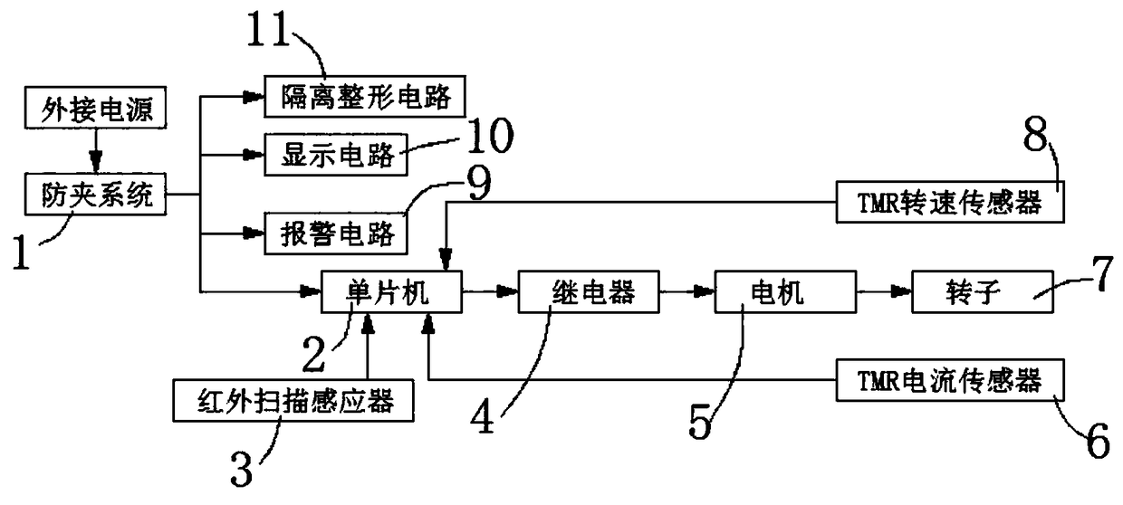
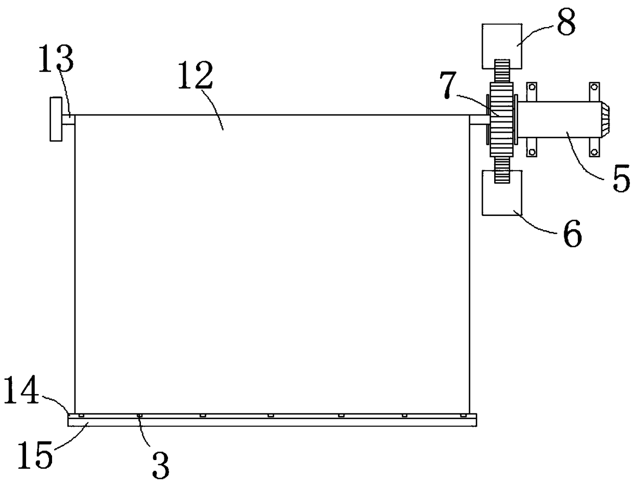
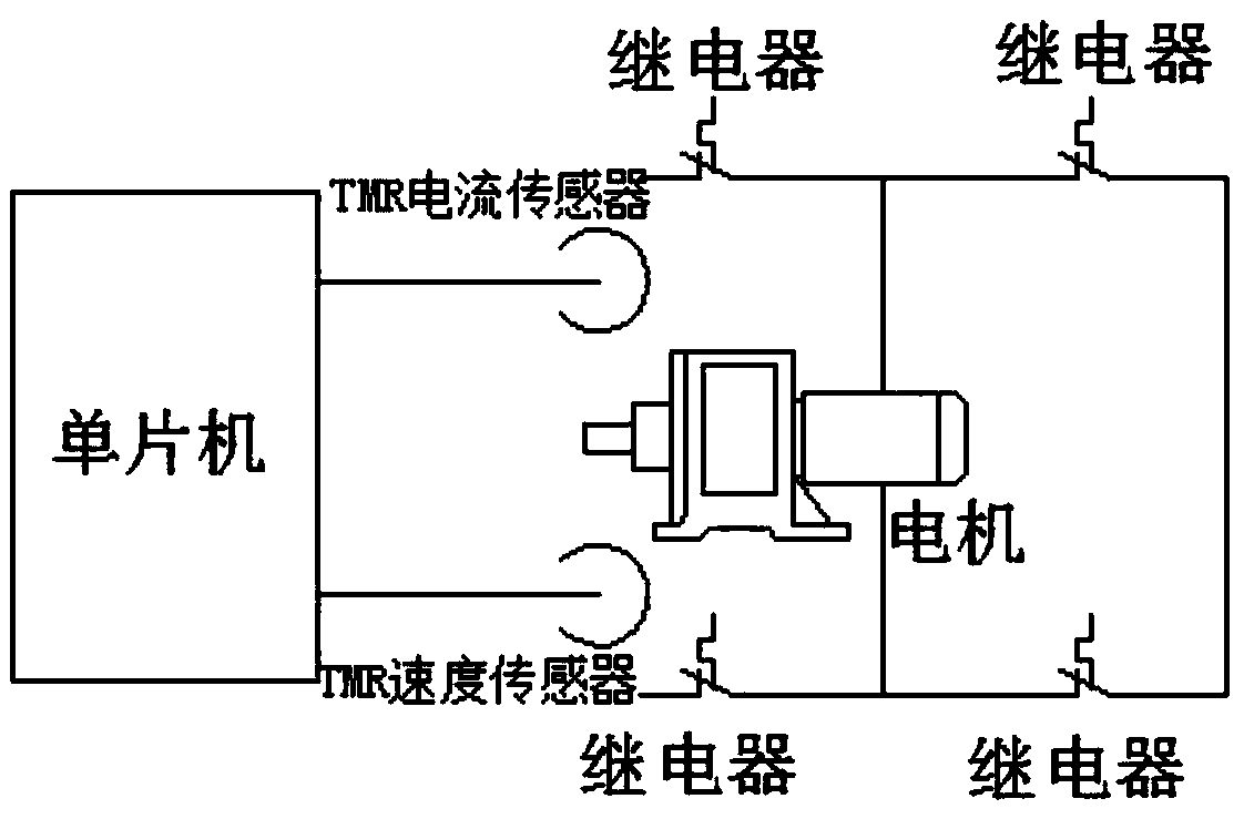
[0026] see Figure 1-5 , the present embodiment provides a TMR magnetoresistive sensor anti-pinch mechanism, including an anti-pinch system 1, and the anti-pinch system 1 includes an isolation shaping circuit 11, a display circuit 10, an alarm circuit 9 and a single-chip microcomputer 2, and the signal input port of the single-chip microcomputer 2 is connected with TMR rotational speed sensor 8, TMR current sensor 6 and infrared scanning sensor 3, the signal output port of single-chip microcomputer 2 is connected with relay 4, and the signal output port of relay 4 is connected with motor 5, and motor 5 includes rotor 7, and motor 5 passes mounting plate Fixed on the top side wall of the door frame, the motor 5 is connected with a rotating roller 13, and the other end of the rotating roller 13 is rotatably connected with the top side wall of the door frame, and the anti-theft rolling door 12 is wound around the rotating roller 13, and the bottom surface of the anti-theft rolling...

Embodiment 2

[0034] see Figure 1-5 , made further improvements on the basis of Embodiment 1: the anti-pinch system 1 is connected to an external power supply through a wire, and the entire circuit is connected to electricity through an external power supply, the motor 5 is a servo motor, and the TMR speed sensor 8 and the TMR current sensor 6 are respectively located at The upper and lower sides of the rotor 7 are arranged in this way to facilitate induction detection of the rotational speed and current of the motor 5. The TMR rotational speed sensor 8 and the TMR current sensor 6 are respectively located on the upper and lower sides of the rotor 7. Several infrared scanning sensors 3 are located at a distance from the front end of the anti-theft rolling door 12. The distance between the planes is 1.5cm, and the purpose of this is to make several infrared scanning sensors 3 not be affected by the anti-theft rolling door 12 in the process of scanning, that is to say, when in the anti-pinch ...


PUM


Abstract

The invention discloses an anti-clamping mechanism of a TMR magneto-resistance sensor, which comprises an anti-clamping system, wherein the anti-clamping system comprises an isolation shaping circuit,a display circuit, an alarm circuit and a single-chip computer, a signal input port of the single-chip computer is connected with a TMR rotating speed sensor, a TMR current sensor and an infrared scanning inductor, a signal output port of the single-chip computer is connected with a relay, a signal output port of the relay is connected with a motor, the motor comprises a rotor, the motor is fixedly arranged on a side wall of a top end of a door frame through a mounting plate, the motor is connected with a rotating roller, the other end of the rotating roller is rotatably connected with the side wall of the top end of the door frame, an anti-theft rolling door is wound on the rotating roller, and a buffer plate is horizontally and fixedly arranged on the bottom end surface of the anti-theft rolling door. The mechanism uses a mode of outputting pulse counting by using the TMR magneto-resistance sensor, the combination of detecting the rotating speed of the motor and detecting the current change condition of the motor is achieved, and the anti-clamping function is achieved.

Description

technical field [0001] The invention relates to the technical field related to intelligent anti-clamping, in particular to an anti-clamping mechanism of a TMR magnetoresistive sensor. Background technique [0002] With the advancement of Internet of Things technology, the components and assemblies of smart containers are also developing towards mechatronics. A large number of electronic devices are used in smart cabinets. For the convenience of customers, a large number of smart cabinets use electric doors, and potential dangers also follow. Events of electric doors pinching fingers happen from time to time, and electric doors do not have anti-pinch functions. Cause harm to customers, especially children. For the sake of safety, it is absolutely necessary to develop an automatic door control module with anti-pinch function for smart containers, and the anti-pinch function has become an inevitable trend. [0003] At present, the electric door anti-pinch device mainly adopts...

Claims


Application Information

Patent Timeline
Patent Type & Authority Applications(China)
IPC IPC(8): E06B9/68E06B9/70
CPCE06B9/68E06B9/70E06B2009/6836
Inventor 张毅刚何雄张亚
Owner 上海容之科技集团有限公司
Why Eureka
Try Eureka