An Explosion-proof Centrifuge Conducive to Improving Work Safety

A safe and explosion-proof technology, applied in the centrifugal field, can solve problems such as potential safety hazards, no explosion-proof treatment of electrical components, and manual operation of opening and closing the safety cover.

Active Publication Date: 2021-04-20
山东龙兴石油设备有限公司
View PDF7 Cites 0 Cited by
  • Summary
  • Abstract
  • Description
  • Claims
  • Application Information

AI Technical Summary

Problems solved by technology

[0002] Centrifugal measuring instruments are mostly used in laboratory operations in the petroleum, petrochemical, and natural gas industries. There are potential safety hazards. The operation

Method used


Image

  • An Explosion-proof Centrifuge Conducive to Improving Work Safety
  • An Explosion-proof Centrifuge Conducive to Improving Work Safety
  • An Explosion-proof Centrifuge Conducive to Improving Work Safety

Examples


Embodiment 1

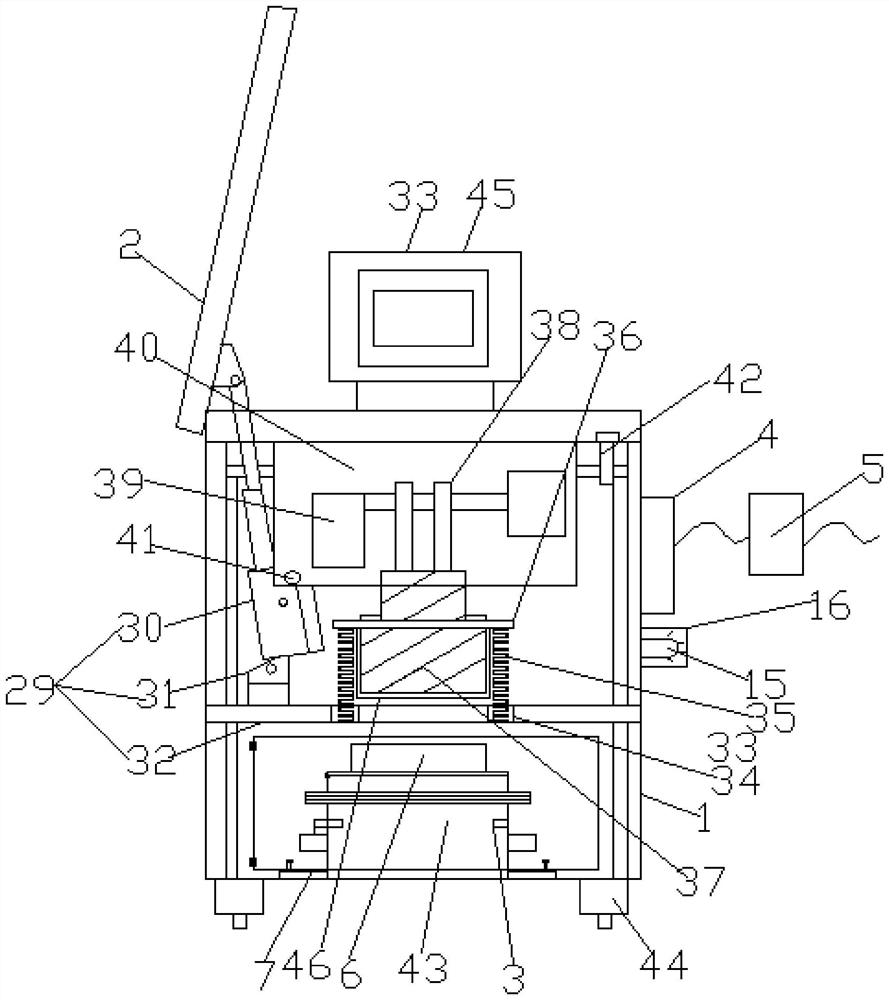
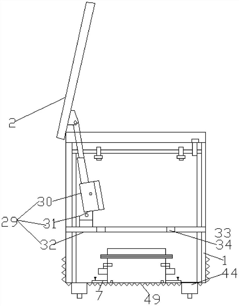
[0031] see Figure 1-6 , according to an embodiment of the present invention, an explosion-proof centrifuge that is conducive to improving work safety includes a sheet metal casing 1 and a box cover 2, and an upper cover is provided between the sheet metal casing 1 and the box cover 2 Drive module 29, the upper cover drive module 29 includes a potentiometer type electric push rod 30, the box cover 2 and the top side of the sheet metal casing 1 are linked by a link, the potentiometer type electric push rod 30 The output top end of the push rod 30 is hingedly connected with the inner bottom end of the box cover 2 through a movable connection. Frame 32, the bottom of the connecting block 31 forms a hinge connection with the frame 32 through a movable link, and the frame 32 is provided with several spring grooves 34, and springs 35 are fixed in the spring groove 34, so that The top of the spring 35 is fixedly provided with a setting plate 36, and the central position of the botto...

Embodiment 2

[0033] see figure 1 , for the alarm 15, the alarm 15 includes an external protective housing 16 and an alarm device arranged in the protective housing 16.

[0034] Through above-mentioned scheme of the present invention, beneficial effect: the setting of protective case 16 is protected alarm 15, and does not affect the use of alarm 15.

Embodiment 3

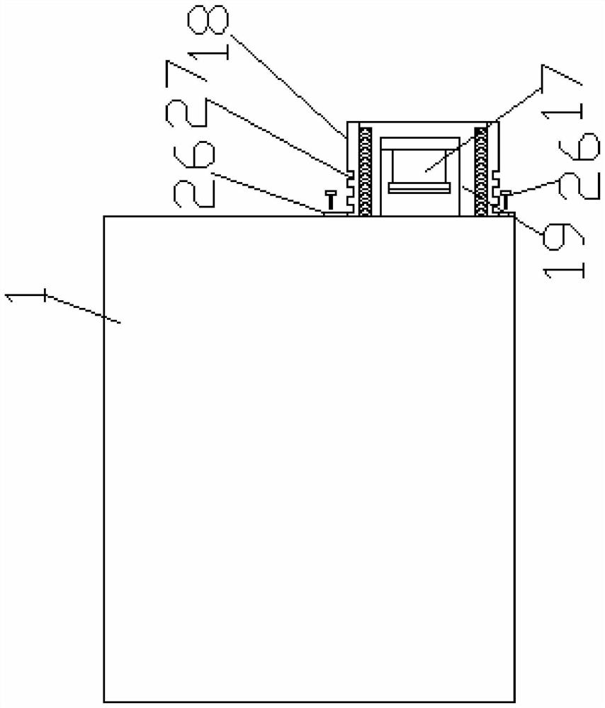
[0036] see Figure 3-4 , for the sheet metal casing 1, the sheet metal casing 1 is provided with an explosion-proof joint 17, and the outer wall of the sheet metal casing 1 is provided with a circular sleeve 18, and the material of the circular sleeve 18 is Sheet metal circular shell, and the interior of the circular sleeve 18 is a cavity structure, the explosion-proof joint 17 is sleeved in the circular sleeve 18, the explosion-proof joint 17 and the circular sleeve A cavity 19 is formed between 18, and the inner wall of the cavity 19 is fixedly pasted with an activated carbon filter screen 20, and the outer wall of the circular sleeve 18 is fixedly provided with a docking cylinder 21, and the explosion-proof joint 17 is connected to a wire joint 22, so The wire joint 22 is connected with a wire 23, and the wire 23 is fixedly sleeved with a secondary docking cylinder 24 that matches the docking cylinder 21, and the secondary docking cylinder 24 is fixedly pasted on one end of...


PUM


Abstract

The invention discloses an explosion-proof centrifuge which is beneficial to improve work safety, comprising a sheet metal casing and a box cover, an upper cover driving module is arranged between the sheet metal casing and the box cover, and the upper cover The drive module includes a potentiometer-type electric push rod, and the box cover is connected with the top side of the sheet metal casing through a link, and the output top of the potentiometer-type electric push rod is connected to the box through a flexible connection. The inner bottom end of the cover forms a hinge connection. Beneficial effects: Note that the output end of the explosion-proof motor passes through the setting plate and the bottom of the protective cover and extends into the protective cover. The vibration generated when the explosion-proof motor is working is damped by the set spring, and the explosion-proof motor and the setting plate are connected by the spring For setting, the number of springs is set to several.

Description

technical field [0001] The invention relates to the field of centrifugation, in particular to an explosion-proof centrifuge which is beneficial to improving work safety. Background technique [0002] Centrifugal measuring instruments are mostly used in laboratory operations in the petroleum, petrochemical, and natural gas industries, which has potential safety hazards. The operation of the safety cover needs to be completed manually. At present, the electrical components of the existing equipment are not explosion-proof. The opening and closing of the safety cover are all manual operations. [0003] Aiming at the problems in the related technologies, no effective solution has been proposed yet. Contents of the invention [0004] The object of the present invention is to provide an explosion-proof centrifuge that is beneficial to improve work safety, so as to solve the problems raised in the above-mentioned background technology. [0005] To achieve the above object, the ...

Claims


Application Information

Patent Timeline
IPC IPC(8): B04B7/06B04B7/02B04B15/00B04B15/02B04B13/00
CPCB04B7/02B04B7/06B04B13/00B04B15/00B04B15/02B04B2007/025B04B2013/006
Inventor 王跃刚舒莘格李云谢宗豪张允兴
Owner 山东龙兴石油设备有限公司
Why Eureka
Try Eureka