

Three-side plastic frame size detecting device
A technology of size detection and edge rubber frame, which is applied in the direction of measuring device, optical device, workpiece clamping device, etc., can solve the problems of unsatisfactory modernization and plastic frame distortion, and achieve the effect of optimizing detection and reducing data errors
- Summary
- Abstract
- Description
- Claims
- Application Information
AI Technical Summary
Problems solved by technology
Method used
Image


Examples
Embodiment 1
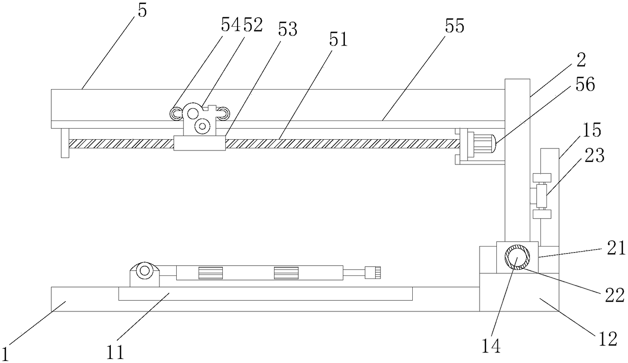
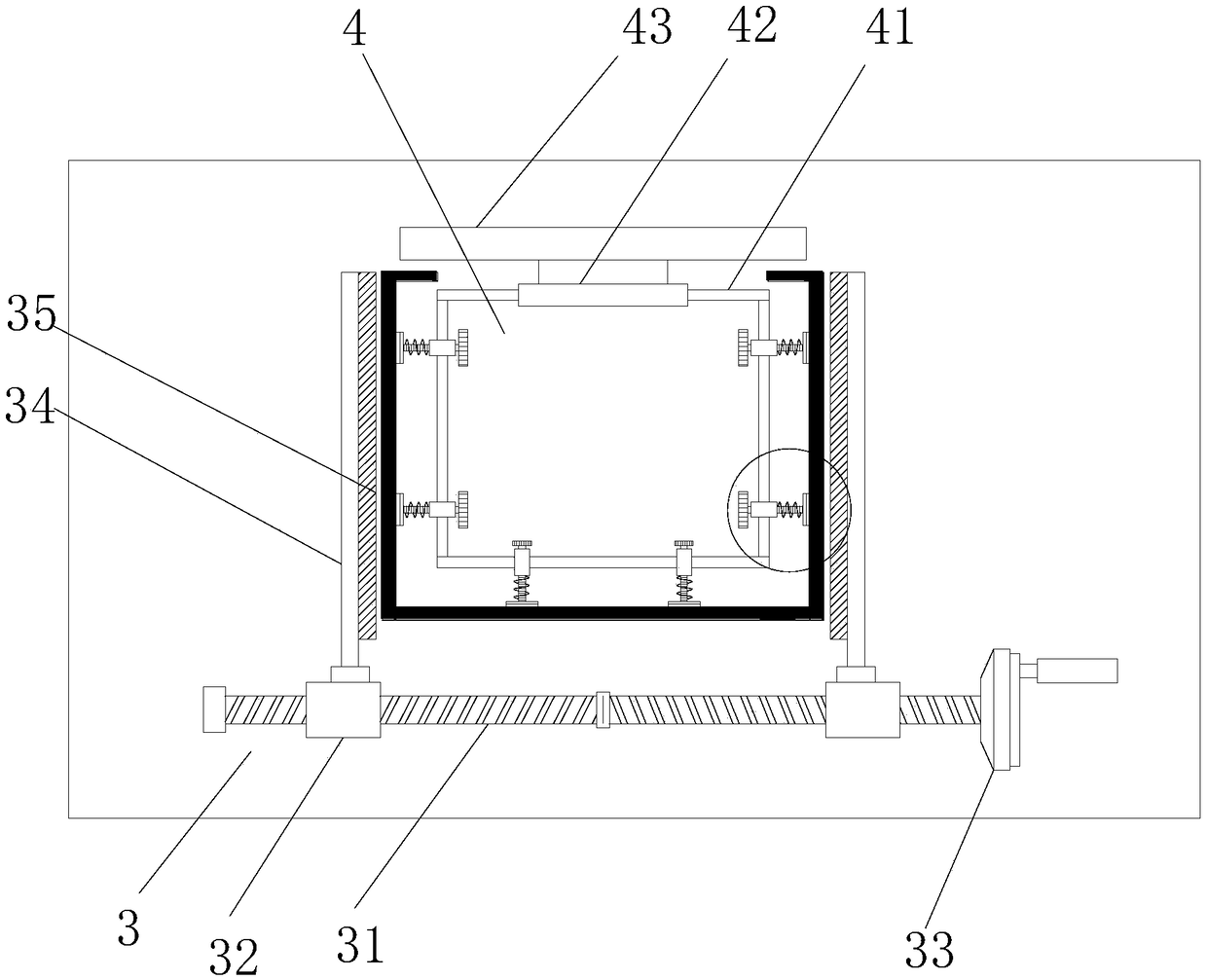
[0025] see figure 1 and image 3 , Figure 4 , a size detection device for a three-sided rubber frame, comprising a machine 1, a detection frame 2 is installed on the top of the machine 1, a detection substrate 11 is installed on the table of the machine 1, and a detection substrate 11 is installed on the detection substrate 11. An outer limit mechanism 3 and an inner limit mechanism 4 are respectively provided, the outer limit mechanism 3 includes a limit splint 34, a transmission sleeve 32 is installed on the plane of the detection substrate 11, and a transmission sleeve 32 is pierced inside the transmission sleeve 32. Threaded column 31, the transmission threaded column 31 is a two-way thread structure, the middle position of the transmission threaded column 31 is provided with a partition, the transmission threaded column 31 takes the partition as the center line and the directions of the external threads of the left and right sections are opposite, so The transmission s...
Embodiment 2
[0028] see figure 1 and figure 2 , this embodiment is a further optimization of Embodiment 1. On the basis of it, a slide block 21 is installed at the bottom end of the detection frame 2, and a threaded hole 22 is arranged inside the slide block 21. The machine table 1 A chute 12 is installed on the side, and the slider 21 is limited in the chute 12. A first-stage transmission screw 14 is transversely pierced in the chute 12, and the slider 21 is sleeved on the first-stage transmission screw. 14, a driving motor 13 is installed on the side of the machine table 1, and the motor shaft of the first-stage transmission screw 14 is connected with the driving motor 13 through a coupling. A transmission frame 5 is installed on the top of the detection frame 2, and a secondary transmission lead screw 51 is horizontally installed on the transmission frame 5. A detection seat 52 is synchronously installed on the transmission frame 5, and a detection seat 52 is installed on the transmis...
PUM
 Abstract
Description
Claims
Application Information