Automatic centering device of electric spindle reliability test platform based on drag loading

An automatic centering and drag loading technology, which is used in measuring devices, testing of mechanical components, testing of machine/structural components, etc. It can solve the problems of time-consuming, inability to monitor the generation and elimination of singular data in time, etc. To achieve the effect of short adjustment time, saving test cost and ensuring accuracy

Active Publication Date: 2019-03-19
JILIN UNIV
View PDF16 Cites 7 Cited by
  • Summary
  • Abstract
  • Description
  • Claims
  • Application Information

AI Technical Summary

Problems solved by technology

[0005] The technical problem to be solved by the present invention is to overcome the problem that the existing technology cannot timely monitor the generation and elimination of singular data in the test and artificially adjust the centering of the test bench, which will consume a lot of manpower and time. Automatic centering device for drag-loaded electric spindle reliability test bench

Method used


Image

  • Automatic centering device of electric spindle reliability test platform based on drag loading
  • Automatic centering device of electric spindle reliability test platform based on drag loading
  • Automatic centering device of electric spindle reliability test platform based on drag loading

Examples


Embodiment Construction

[0038] The present invention is described in detail below in conjunction with accompanying drawing:

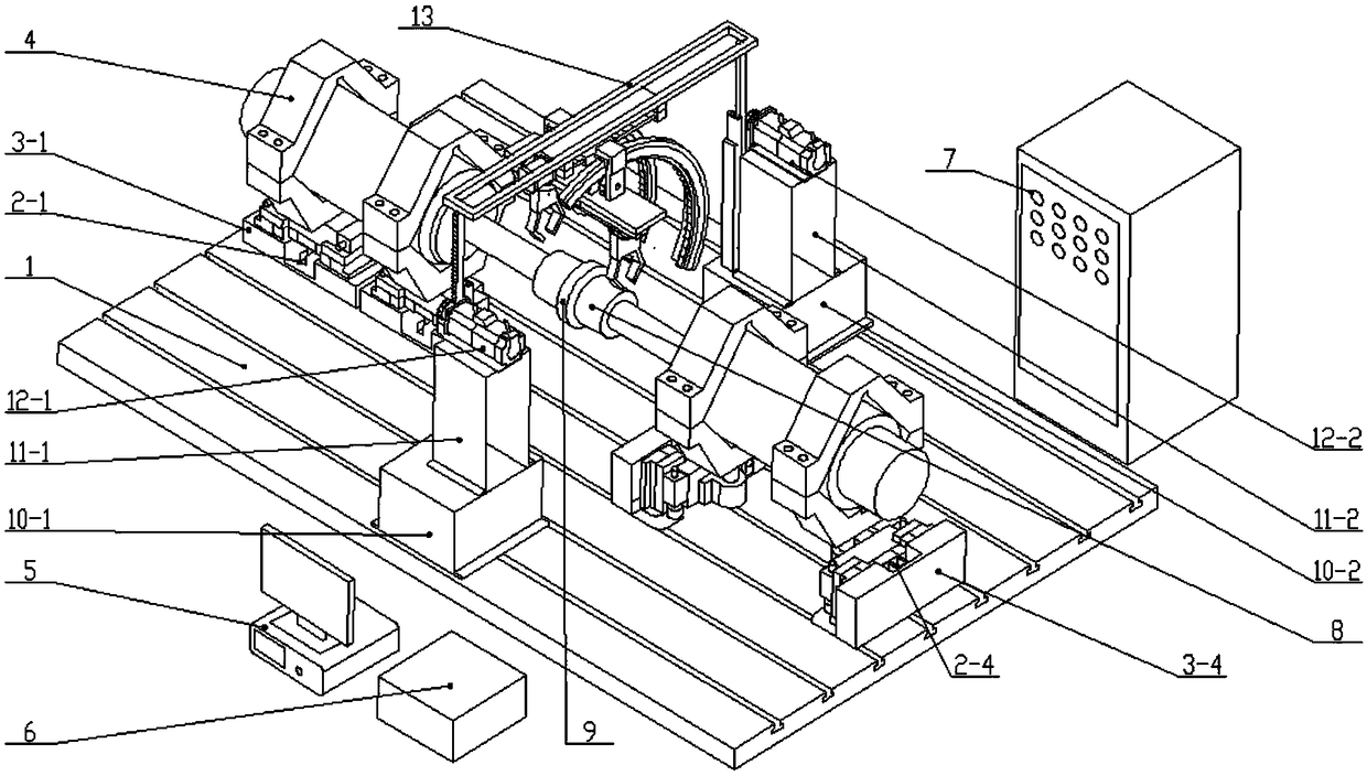
[0039] Since the alignment of the two tested spindles cannot be detected during the test, the alignment of the two tested spindles is usually detected at the beginning and end of the test, but the detection results at the end of the test are usually misalignment The difference has exceeded the maximum value required by the test bench stress, which leads to the generation of data singularities and it is impossible to determine when the test bench starts to generate singular data. In other words, it is impossible to determine which data is exceeding the test bench. It is generated under the condition of misalignment, and all test data will be invalidated. However, artificially detecting and adjusting the alignment of the test bench will interrupt the reliability test for a long time and affect the test efficiency. When the test is stopped, it is likely that the misalignment has ...


PUM


Abstract

The invention discloses an automatic centering device of an electric spindle reliability test platform based on drag loading, and aims to solve the problems of incapable of timely monitoring generation of singularity and elimination and time and labor wasting when adjusting centering of the test platform, the device comprises a spindle position adjusting part, a detection part and a monitoring andautomatic control part; the detection part comprises a supporting device, a feeding device and a detection device; the spindle position adjusting part is arranged at the middle position of an horizoniron through a first to forth static pressure sliding platform, wherein the first static pressure sliding platform and the second static pressure sliding platform are arranged at the left side of thehorizon iron, and the third static pressure sliding platform and the fourth static pressure sliding platform are arranged at the right side of the horizon iron; the detection part is arranged at themiddle position of the horizon iron through a first supporting base and a second supporting base, supporting devices are arranged at the front side and rear side of the spindle position adjusting part, and the feeding device is arranged on the supporting devices; a first laser centering instrument and a second laser centering instrument in the detection device are fixed on a fixing plate in the feeding device; and the monitoring and automatic control part is connected with the spindle position adjusting part and the detection part through wires.

Description

technical field [0001] The invention relates to an automatic centering device, more precisely, the invention relates to an automatic centering device for an electric spindle reliability test bench based on dragging. Background technique [0002] As the industrial mother machine of mechanical manufacturing, CNC machine tools usually represent the level of a country's manufacturing industry. However, my country's high-end CNC machine tool market has been dominated by imported CNC machine tools. The main reason is that domestic CNC machine tools have poor reliability and low precision retention. The problem of the reliability of CNC machine tools has limited the development of my country's own brand CNC machine tools, so improving the reliability of domestic CNC machine tools is of great significance to the development of my country's CNC machine tool industry. [0003] The reliability level of CNC machine tools is largely determined by the reliability level of key functional ...

Claims


Application Information

Patent Timeline
Patent Type & Authority Applications(China)
IPC IPC(8): G01M13/00
CPCG01M13/00
Inventor 赵泓荀陈传海杨兆军何佳龙李国发王继利陈菲王彦鹍许彬彬朱晓翠田海龙应骏李世拯郭劲言
Owner JILIN UNIV
Why Eureka
Try Eureka