A 3D Visual Scalp Craniotomy Positioning Method Combined with Optical Surgical Navigation

A technique of surgical navigation and positioning method, which is applied in the field of 3D visualization scalp craniotomy positioning combined with optical surgical navigation, and can solve the problems of large angle between surgical tools and scalp, inaccurate incision design, and inability to delineate and correct results.

Active Publication Date: 2021-10-26
SOUTH CHINA UNIV OF TECH
View PDF1 Cites 1 Cited by
  • Summary
  • Abstract
  • Description
  • Claims
  • Application Information

AI Technical Summary

Problems solved by technology

However, observing the outline of the lesion from a single three-dimensional perspective will lead to a large angle between the surgical tool and the scalp, and it is easy to cause inaccurate incision design due to improper operation; at the same time, the mainstream surgical navigation system does not provide feedback on the contouring process. Therefore, it is not possible to correct the sketching results
In addition, there is currently no standardized set of contour delineation evaluation methods to quantify the results of the incision design

Method used


Image

  • A 3D Visual Scalp Craniotomy Positioning Method Combined with Optical Surgical Navigation
  • A 3D Visual Scalp Craniotomy Positioning Method Combined with Optical Surgical Navigation
  • A 3D Visual Scalp Craniotomy Positioning Method Combined with Optical Surgical Navigation

Examples


Embodiment Construction

[0035] The present invention will be further described below in conjunction with specific examples.

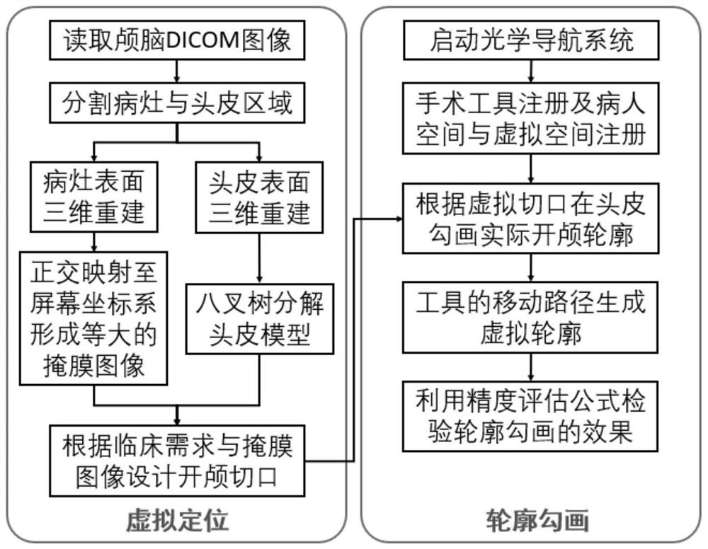
[0036] Such as figure 1 As shown, the three-dimensional visual scalp craniotomy positioning method combined with optical surgical navigation provided in this embodiment includes the following steps:

[0037] 1) Obtain two-dimensional medical image slices from the imaging device, segment the scalp and lesion area in the image, reconstruct the scalp and the lesion to construct a three-dimensional model, and the specific steps are:

[0038] 1.1) Read the two-dimensional slice image of the brain;

[0039] 1.2) Anisotropic filtering is used to process the slice image, which not only removes noise information, but also retains edge details;

[0040] 1.3) According to the CT value of the scalp, use the threshold method to quickly extract the scalp contour of each slice. The lesion is first down-sampled to a low-resolution image through the image pyramid algorithm, and then the ima...


PUM


Abstract

The invention discloses a three-dimensional visualized craniotomy positioning method combined with optical surgical navigation, comprising the steps of: 1) importing a patient's brain CT image sequence for segmentation, and obtaining two-dimensional image data of intracranial lesions and scalp; 2) according to the lesion and The 2D image of the scalp is reconstructed in 3D, rendered into a 3D model in the virtual space, and the lesion model is orthogonally mapped to the scalp to design an adaptive craniotomy contour; 3) Combining with the optical surgical navigator, the registration of surgical tools and the patient space and patient space are completed. After registration in the virtual space, the surgical tool is tracked in real time, and the actual craniotomy contour is drawn on the real cranial scalp along the virtual craniotomy contour; 4) The moving path of the needle tip of the surgical tool is recorded and displayed in real time by a visual method; 5) In the virtual space, calculate the distance between the actual contour and the designed contour to evaluate the accuracy of craniotomy positioning. The invention provides a reference for doctors to outline, and breaks through the shortcomings of the traditional method of designing craniotomy outlines by staring at the lesion with the naked eye.

Description

technical field [0001] The invention relates to the technical field of medical image processing and surgical application, in particular to a three-dimensional visual scalp craniotomy positioning method combined with optical surgical navigation. Background technique [0002] Craniocerebral surgery has the characteristics of high risk and high difficulty. Locating the craniotomy incision according to the location of the lesion is an important step in craniotomy. The accuracy of positioning will directly affect the quality of the operation and the postoperative recovery of the patient. Neurosurgeons usually use tumor information displayed by CT, MRI and other medical images, and rely on clinical experience to design craniotomy incisions and then remove lesions. During preoperative planning, it is difficult to precisely locate the tumor based on two-dimensional image data, which often results in a too large incision design or inaccurate positioning, which may lead to the need to...

Claims


Application Information

Patent Timeline
Patent Type & Authority Patents(China)
IPC IPC(8): G16H20/40G06T7/13G06T7/73G06T17/00
CPCG06T17/005G06T2207/10081G06T2207/20016G06T2207/30016G06T2207/30096G06T7/13G06T7/73G16H20/40
Inventor 杨荣骞戴知宇杭飞庄建
Owner SOUTH CHINA UNIV OF TECH
Why Eureka
Try Eureka