
A switchgear safety isolation device and method

A technology of safe isolation and switchgear, applied in switchgear, electrical components, etc., to achieve the effect of simple structure, small weight, and not easy to damage or lose.

Active Publication Date: 2020-03-24
STATE GRID CORP OF CHINA +1
View PDF7 Cites 0 Cited by
  • Summary
  • Abstract
  • Description
  • Claims
  • Application Information

AI Technical Summary

Problems solved by technology

[0004] In order to overcome the deficiencies in the prior art, the present invention provides a switch cabinet safety isolation device and method, which mainly solves the problem of safety isolation when working on the top of the switch cabinet, and the device is convenient to store and carry

Method used


Image

  • A switchgear safety isolation device and method
  • A switchgear safety isolation device and method
  • A switchgear safety isolation device and method

Examples


Embodiment 1

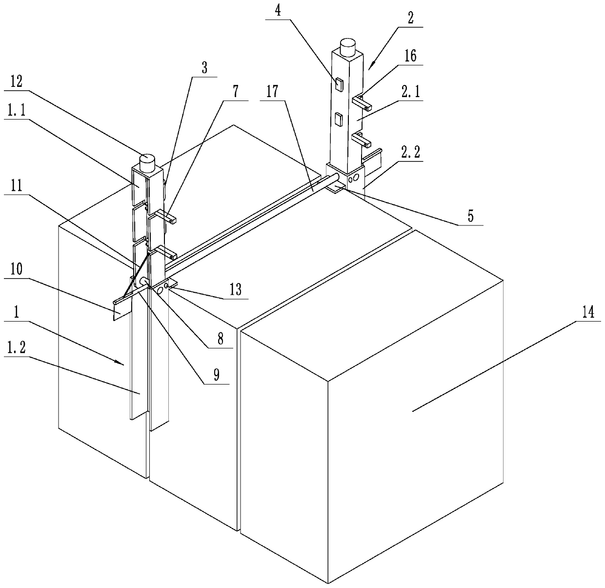
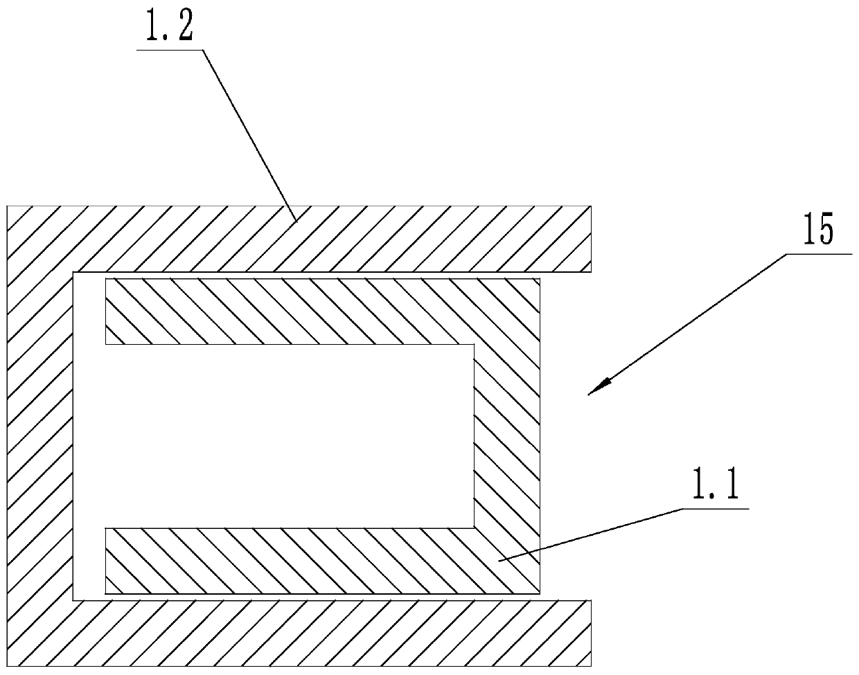
[0029]A safety isolating device for a switch cabinet, comprising a first support rod 1 and a second support rod 2, the first support rod 1 and the second support rod 2 are arranged on opposite sides of a switch cabinet 14, and the upper end of the first support rod 1 is higher than The top of the switch cabinet 14, the upper end of the second support rod 2 is higher than the top of the switch cabinet 14, the first support rod 1 includes the first upper support rod 1.1 and the first lower support rod 1.2, the first upper support rod 1.1 and the first lower support rod The brace 1.2 is hinged; the second brace 2 includes a second upper brace 2.1 and a second lower brace 2.2; the second upper brace 2.1 and the second lower brace 2.2 are hinged; the first lower brace 1.2 is connected to the switch cabinet 14 connection, the first upper strut 1.1 is provided with a telescopic isolation belt 3, the second lower strut 2.2 is connected with the switch cabinet 14, the second upper strut...

Embodiment 2

[0039] A switch cabinet safety isolation method, using the above-mentioned switch cabinet safety isolation device, comprising the following steps:

[0040] a. Preparation before installation: unfold the first upper strut 1.1 and the first lower strut 1.2;

[0041] b. Installation: install the first support rod 1 and the second support rod 2 on opposite sides of the switch cabinet 14 respectively;

[0042] U. Expanding the telescopic belt: pull out the telescopic isolation belt 3 on the first upper strut 1.1, and snap it into the isolation belt buckle 4 on the second upper strut 2.1;

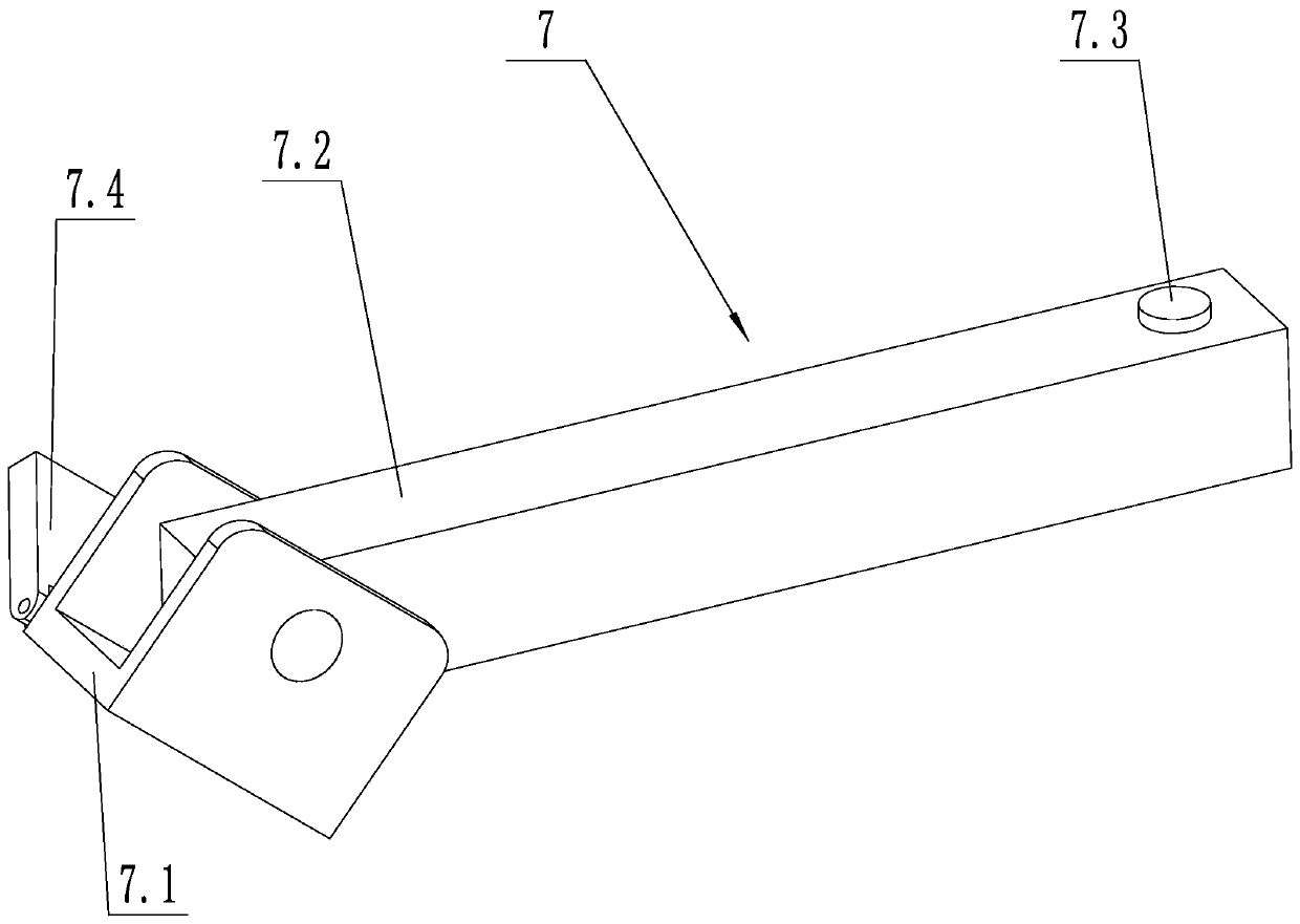
[0043] d. Expand the detector: unfold the mounting base 7.1 and the mounting rod 7.2, snap the mounting rod 7.2 into the clamping gap 16, and turn on the power of the sensor;

[0044] e. Disassembly: after use, disassemble and fold the device from the switch cabinet 14 .

[0045] The beneficial effects of the present invention are: the top of the switchgear can be safely isolated; the structure...


PUM


Abstract

The invention discloses a switch cabinet safety isolation device and method. The device comprises a first support rod and a second support rod. The first support rod and the second support rod are arranged on two opposite sides of a switch cabinet. The upper end of the first support rod is higher than the top of the switch cabinet. The upper end of the second support rod is higher than the top ofthe switch cabinet. The first support rod comprises a first upper strut and a first lower strut. The first upper strut and the first lower strut are hinged. The second support rod comprises a second upper strut and a second lower strut. The second upper strut and the second lower strut are hinged. The first lower strut is connected with the switch cabinet. The first upper strut is provided with atelescopic isolation belt. The second lower strut is connected with the switch cabinet. The second upper strut is provided with an isolation belt buckle. One end of the telescopic isolation belt is buckled with the isolation belt buckle. According to the switch cabinet safety isolation device and method, safety isolation is realized during top operation of the switch cabinet; and the device is convenient for storage and carrying.

Description

technical field [0001] The invention relates to the technical field of power equipment maintenance tools, in particular to a switch cabinet safety isolation device and method. Background technique [0002] Switch cabinets are widely used electrical equipment in power systems, especially in 35kV and 10kV voltage levels. Therefore, the maintenance work of the switchgear is particularly important. However, due to its fully enclosed nature, the inside of the switchgear cannot be seen at ordinary times, and accidents are prone to occur. Therefore, safety measures should be taken before the switchgear is overhauled to ensure the safety of the staff. At present, the safety measures of the switchgear in the substation include ordinary telescopic fences, red and white belts, etc. These safety measures are mainly aimed at the work of the switchgear on the ground, which can isolate live equipment and protect the personal safety of the staff. But when the workers work on the top of t...

Claims


Application Information

Patent Timeline
Patent Type & Authority Patents(China)
IPC IPC(8): H02B3/00
CPCH02B3/00
Inventor 周刚高惠新周迅何升华李传才张斌郭建峰戚中译黄杰
Owner STATE GRID CORP OF CHINA
Learn More