Terminal and assembling method thereof

An assembly method and terminal technology, which can be applied to the structure of telephones, telephone communications, instruments, etc., can solve the problems of poor flexibility, inability to flexibly adjust the curvature of the screen, and failure to take into account the bending protection of flexible screens, etc.

Inactive Publication Date: 2019-03-19
NUBIA TECHNOLOGY CO LTD
View PDF8 Cites 9 Cited by
  • Summary
  • Abstract
  • Description
  • Claims
  • Application Information

AI Technical Summary

Problems solved by technology

[0003] First, the bending protection of the flexible screen of the terminal is not considered, and the user can bend it arbitrarily, which is very easy to cause damage to the flexible screen
[0004] Second, although the bending resistance of the flexible scre

Method used


Image

  • Terminal and assembling method thereof
  • Terminal and assembling method thereof
  • Terminal and assembling method thereof

Examples


no. 1 example

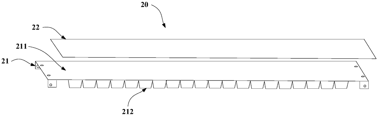
[0061] In order to solve the defect that the existing flexible screen terminal has no bending protection during the bending process and is prone to excessive bending damage, an embodiment of the present invention provides a terminal. Please refer to figure 2 , figure 2 It is a schematic structural diagram of a terminal provided by an embodiment of the present invention. The terminal 20 includes a bendable housing 21 and a flexible screen assembly 22 fixedly arranged on the upper surface 211 of the bendable housing 21 . Wherein, the flexible screen assembly 22 can be fixedly arranged on the upper surface 211 by bonding, for example, by bonding foam glue or other soft glue on the upper surface 211, so that the flexible housing 21 and the flexible screen assembly 22 can be Bend or flatten together.

[0062] The upper surface 211 of the flexible housing 21 can be an elastic metal sheet, such as an elastic steel sheet. The shape of the upper surface 211 can be rectangular, and t...

no. 2 example

[0087] An embodiment of the present invention provides a terminal assembly method for assembling the terminal described in the first embodiment above, please refer to Figure 18 , including the following steps:

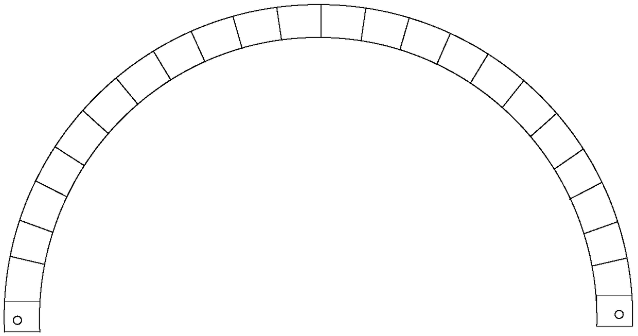
[0088] S181. The opposite sides of the bendable housing are symmetrically provided with sawtooth-shaped limiting structures, and the sawtooth-like limiting structures include a plurality of sawtooth blocks of the same shape and size, so that the opposite sides of the bendable housing are symmetrical The connection between the two sawtooth blocks is realized by welding a volume block, and an accommodating cavity is formed between the bendable shell and each volume block.

[0089] S182. Insert two dynamic steel sheets into the accommodation cavity, and connect the left end of one dynamic steel sheet to the bendable casing by screws, and connect the right end of the other dynamic steel sheet to the bendable casing by screws.

[0090] As for the end of the power steel sh...


PUM


Abstract

The invention discloses a terminal and an assembling method thereof. The terminal comprises a bendable shell and a flexible screen module fixedly at an upper surface of the bendable shell; zigzag limiting structures are arranged at two opposite sides of the bendable shell; when the bendable shell is bent, sawtooth blocks included by the zigzag limiting structures mutually close to contact with each other, thereby performing the limiting; in the bending process of the bendable shell, sawtooth block modules on two opposite sides of the bendable shell close to each other, when all adjacent sawtooth blocks are in contact, the continuous bending deformation of the bendable shell is prevented, the overbending of the flexible screen module fixedly arranged on the upper surface of the bendable shell is avoided, and the flexible bending of the flexible screen terminal is realized, the bending protection is performed on the terminal flexible screen, and the problem that the existing flexible screen terminal is easy to be excessively bent and damaged due to the absence of the bending protection is solved.

Description

technical field [0001] The present invention relates to the technical field of flexible screen terminals, and more specifically, to a terminal and an assembly method thereof. Background technique [0002] Nowadays, with the rapid development of flexible screens, flexible terminals have become one of the new research and development hotspots in the mobile phone industry in the future. Flexible screen is OLED (Organic Light-Emitting Diode, Organic Light-Emitting Diode) display screen, which is a screen composed of organic light-emitting diodes, because of its low power consumption, high contrast, wide color gamut, wide viewing angle, thinner and bendable Advantages, it is widely used in next-generation terminal devices, such as flexible screen mobile phones, flexible screen watches, etc., which have the characteristics of bending and deformation. Great bend. Therefore, when a flexible screen is applied to a corresponding terminal device, the bending resistance of the flexibl...

Claims


Application Information

Patent Timeline
IPC IPC(8): H04M1/02G06F1/16
CPCG06F1/1652H04M1/0268
Inventor 李盼里强
Owner NUBIA TECHNOLOGY CO LTD
Why Eureka
Try Eureka