Equipment cabinet liquid cooling system

A liquid-cooled heat dissipation and cabinet technology, which is applied in the direction of cooling/ventilation/heating transformation, electrical components, electrical equipment structural parts, etc., can solve problems such as unfavorable operation of electronic equipment in the cabinet, dust brought into the cabinet, and low heat dissipation efficiency. Achieve the effects of preventing local heat accumulation, promoting air flow, and high heat dissipation efficiency

Active Publication Date: 2019-03-19
ZHEJIANG BENYUE ELECTRIC & TECH
View PDF6 Cites 2 Cited by
  • Summary
  • Abstract
  • Description
  • Claims
  • Application Information

AI Technical Summary

Problems solved by technology

However, the inside of the cabinet is air-cooled to dissipate heat, and the heat dissipation efficiency is low. The space in the computer room is large, and the air conditioner is used for cooling. On the one hand, the energy consumption is very large. Keep the computer room at low temperature and compensate for the heat exchange between the computer room and the outside. In the actual process, the temperature inside the cabinet is much higher than that in the computer room, which is not conducive to the good operation of the electronic equipment inside the cabinet. Moreover, the air conditioner in the computer room consumes a lot of energy, but it does not give the cabinet Bring good heat dissipation effect, resulting in great waste of energy consumption
Moreover, many electronic devices inside the cabinet need to be dust-proof, and the air flow between the cabinet and the computer room can easily bring the dust in the computer room into the cabinet.

Method used


Image

  • Equipment cabinet liquid cooling system
  • Equipment cabinet liquid cooling system
  • Equipment cabinet liquid cooling system

Examples


Embodiment Construction

[0021] The present invention will be further described below in conjunction with accompanying drawing and specific embodiment:

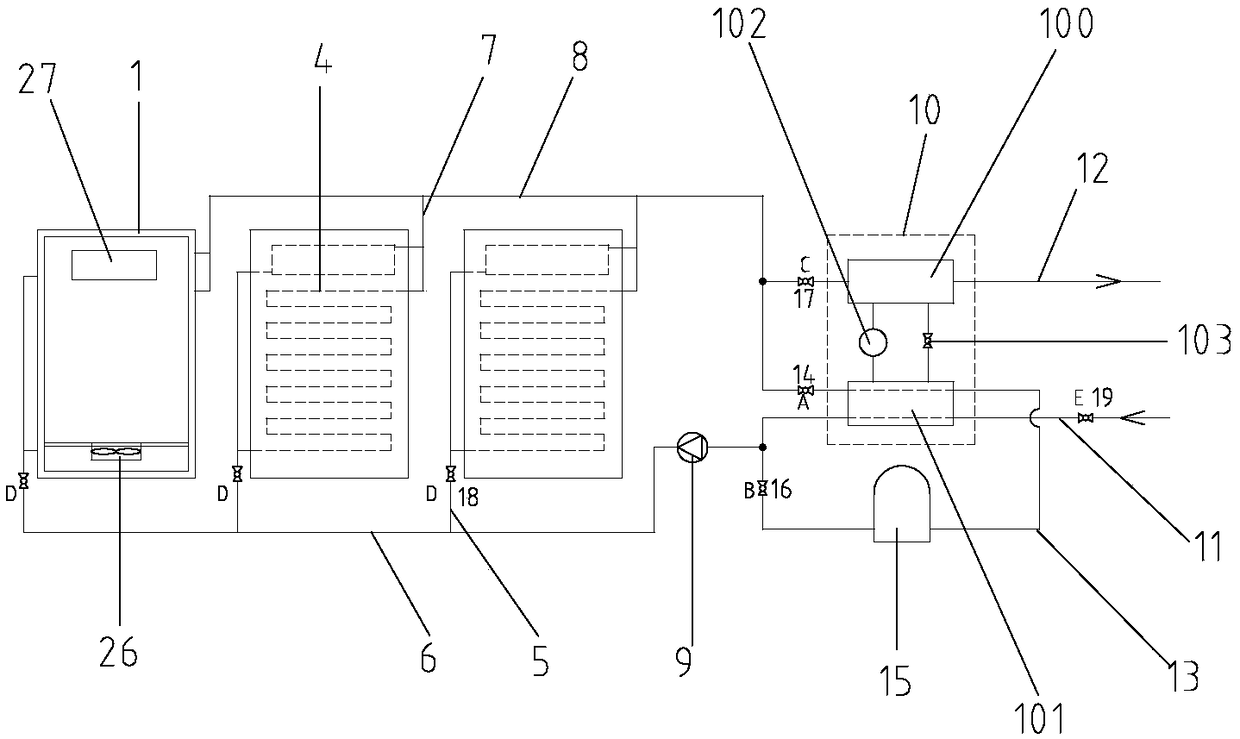
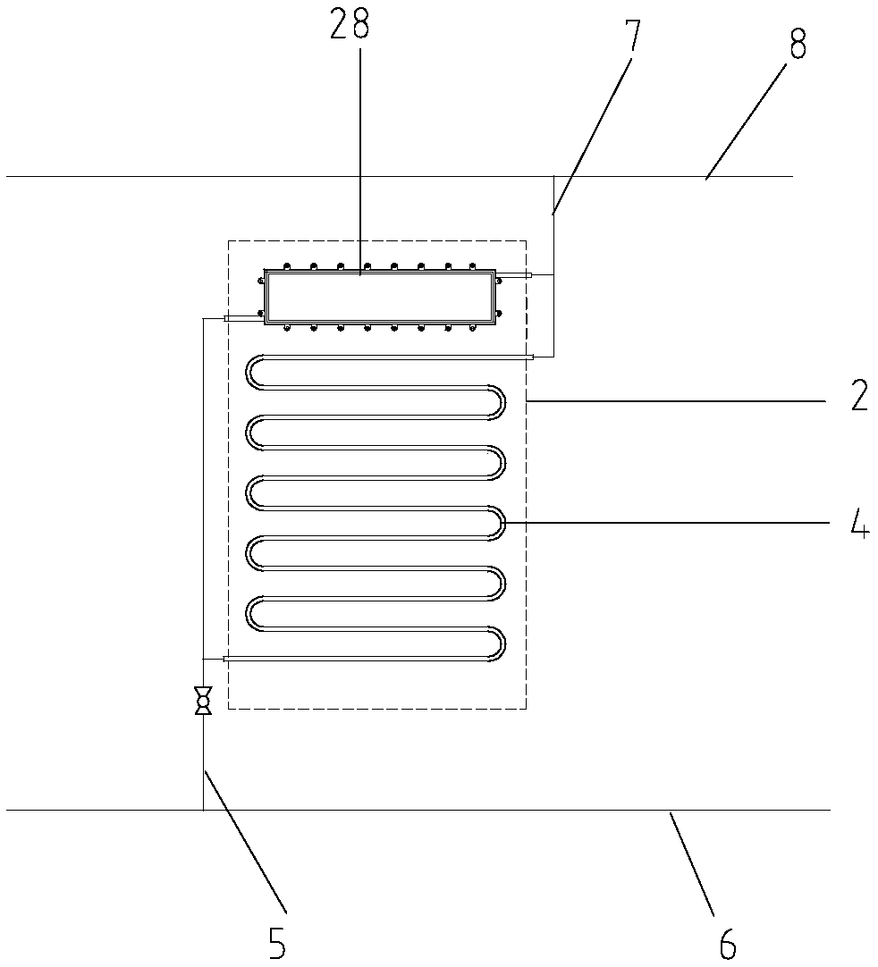
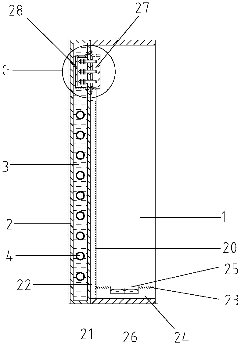
[0022] Such as figure 1 , figure 2 with image 3 The shown cabinet liquid cooling system includes several cabinets 1, the back of the cabinet is provided with a cooling cabinet 2, a cooling chamber 3 is provided in the cooling cabinet, a cooling coil 4 is provided in the cooling chamber, and the lower end of the cooling coil is from The lower side wall of the cooling cabinet protrudes outside the cooling cabinet, the upper end of the cooling coil extends out of the cooling cabinet from the upper side wall of the cooling cabinet, and the cooling cavity is filled with a heat conducting medium, which in this embodiment is heat conducting oil; each The lower ends of the cooling coils on the cabinets are connected to the main water inlet pipe 6 through the water inlet branch pipe 5, and the upper ends of the cooling coils on each cabinet are connected ...


PUM


Abstract

The invention relates to the technical field of equipment cabinet heat dissipation and discloses an equipment cabinet liquid cooling system, which comprises a plurality of equipment cabinets, whereinheat dissipation cabinets is arranged on the back sides of the equipment cabinets; a cooling coil is arranged in a cooling chamber; the cooling chamber is filled with a heat conductive medium; the lower end of the cooling coil on each equipment cabinet is connected to a main water inlet pipe through a branch water inlet pipe; the upper end of the cooling coil on each equipment cabinet is connectedto a main water outlet pipe through a branch water outlet pipe; and a water pump is disposed on the main water inlet pipe. The equipment cabinet liquid cooling system further comprises a double watersource heat pump which includes a condenser and an evaporator, wherein a return pipe is connected between the water outlet end of the main water outlet pipe and the water inlet end of the main waterinlet pipe, passes through the evaporator, and is provided with a valve A; a water tank is arranged between the return pipe and the main water inlet pipe; a valve B is arranged between the water tankand the main water inlet pipe; a valve C is arranged on the water inlet end of a hot water pipe; valves D are arranged on the branch water inlet pipes of respective equipment cabinets; and a valve E is arranged at the water inlet end of a cold water pipe. The equipment cabinet liquid cooling system has high heat dissipation efficiency and good dustproof performance.

Description

technical field [0001] The invention relates to the technical field of cabinet cooling, in particular to a cabinet liquid cooling system. Background technique [0002] At present, in some large computer rooms, there are a large number of cabinets, and various data processors, controllers and other electronic equipment are installed inside the cabinets, which generate a lot of heat, and there are many cabinets in the computer room, and various electronic devices in the cabinets are in operation. A large amount of heat will be generated. If the heat cannot be removed in time, the service life, operating efficiency and stability of the electronic equipment in the cabinet will be reduced, or even malfunction. At present, the computer room is usually air-conditioned and refrigerated throughout the year, and fans are used in the cabinet to exchange heat with the cold air in the computer room, so as to maintain good heat dissipation inside the cabinet. However, the inside of the c...

Claims


Application Information

Patent Timeline
Patent Type & Authority Applications(China)
IPC IPC(8): H05K7/20
CPCH05K7/20645
Inventor 李同强赵中伟余斌霄余金华
Owner ZHEJIANG BENYUE ELECTRIC & TECH
Why Eureka
Try Eureka