Implant recycling device as well as application and packaging thereof

A technology for implants and recovery devices, applied in prostheses, filters in blood vessels, medical science, etc., can solve problems such as stuck, sheath tube orifice stuck, unable to recover, etc., to increase the entrance space, reduce experience and Technical requirements, the effect of improving the success rate of recycling

Pending Publication Date: 2019-03-22
SHENZHEN KYD BIOMEDICAL TECH CO LTD
View PDF19 Cites 1 Cited by
  • Summary
  • Abstract
  • Description
  • Claims
  • Application Information

AI Technical Summary

Problems solved by technology

[0007] One of the purposes of the present invention is to provide a sheath for implant recovery, which can solve the problem that the implant in the prior art is stuck or stuck at the sheath mouth and cannot be recovered when it is recovered into the sheath. High recycling success rate, easy to use

Method used


Image

  • Implant recycling device as well as application and packaging thereof
  • Implant recycling device as well as application and packaging thereof
  • Implant recycling device as well as application and packaging thereof

Examples


Embodiment 1

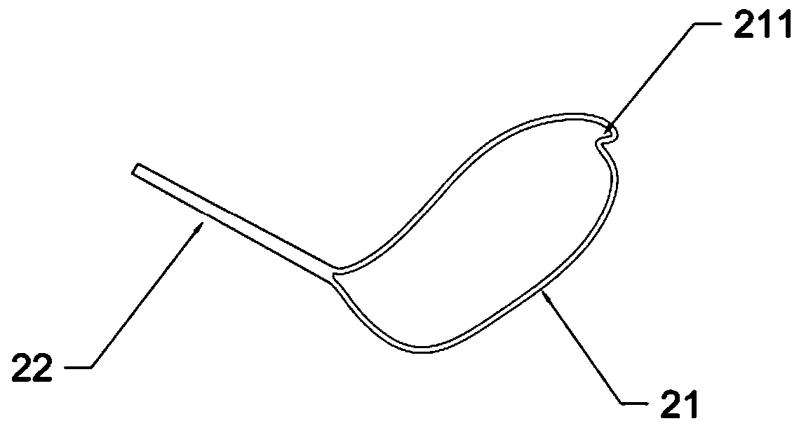
[0080] This embodiment provides a sheath tube 1 for implant recovery. The distal port of the sheath tube 1 for recovery is used for implant entry. The wall of the sheath tube 1 for recovery is provided with a notch 15 at the distal port. The opening of the notch 15 The length 152 is greater than or equal to the length of the bottom 153 of the notch.

[0081] The notch 15 provides an additional entrance for the implant to enter the recovery sheath 1, especially when the implant is received obliquely relative to the tube axis of the recovery sheath 1, the notch increases the relative The permissible range of the aforementioned pipe axis angle.

[0082] Apparently, the shape and size of the notch 15 can be matched according to the shape and size of the recovered implant, so that the implant or its tip can enter the recovery sheath through the notch. The notch 15 may be larger than the outer diameter of the entire implant or its head end, for example, the implant or its head end ...

Embodiment 2

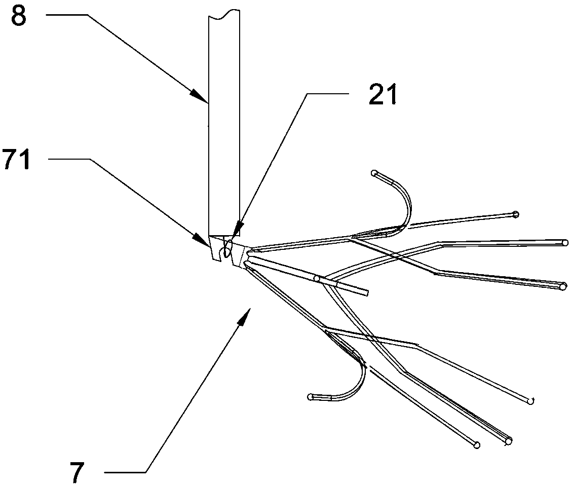
[0090] A preferred embodiment of the sheath 1 for implant retrieval. see Figure 8 , the distal end of the recovery sheath tube 1 is an oblique opening 11, and at both ends of the recovery sheath tube 1 at the oblique opening 11, the protruding end is the oblique opening distal end 111, and the other end is the oblique opening proximal end 112 , the notch 15 is set on the tube wall of the recovery sheath tube 1 on the side near the inclined end 112 .

[0091] The tube wall at the distal end 111 of the oblique opening provides a guiding function for the implant when it is received in the sheath tube 1 for recovery, so that the head of the implant can slide inward along the tube wall at the distal end 111 of the oblique opening.

[0092] see Figure 3-5 , showing a recovery sheath with a beveled distal port, Figure 6-7 The structure of the retrieval sheath distal end assembly is shown. based on Figure 3-5 The shown distal port is designed with a notch for the recovery she...

Embodiment 3

[0095] This embodiment is an improved recovery sheath based on the recovery sheath proposed in Embodiment 1 or 2.

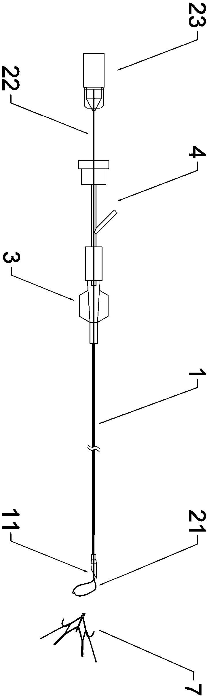
[0096] see Figure 8-10 In this embodiment, an enlarged diameter portion 12 is provided at the distal end of the recovery sheath tube 1, and the inner diameter of the enlarged diameter portion 12 is greater than the inner diameters of other parts of the adjacent recovery sheath tube 1, or the enlarged diameter portion 12 has a recovery sheath The maximum inner diameter of the tube 1, a notch 15 is provided at the distal end of the enlarged diameter part 12, and the enlarged diameter part 12 is used to receive the implant or part thereof. The enlarged diameter portion 12 is beneficial to improve the success rate of introducing the implant or its part into the recovery sheath 1 .

[0097] The enlarged diameter portion 12 of the recovery sheath 1 can be designed in different ways, for example, the diameter can be enlarged by reducing the wall thickness of the enlar...


PUM


Abstract

The invention relates to the technical field of a medical device for intervention operation, in particular to a sheathing canal and recycling apparatus for recycling an implant and an application thereof in recycling an inferior vena cava filter. A remote port of the sheathing canal for recycling the implant is used for the implant to enter, a wall of the sheathing canal for recycling is providedwith a notch on the remote port, and an opening length of the notch is greater than or equal to a bottom length of the notch. An implant catcher comprises the recycling sheathing canal and a catchingunit, and the catching unit is arranged in the recycling sheathing canal in a manner of sliding relative to the recycling sheathing canal and is configured as being capable of entering and existing the remote port of the recycling sheathing canal in a push and pull manner so as to catch the implant. By adopting the implant recycling apparatus, the problem that the implant cannot be recycled due tothe clamping or seizure at the opening of the recycling sheathing canal can be solved, the operation difficulty is low, and the recycling success rate of the implant is high.

Description

technical field [0001] The invention relates to the technical field of medical instruments for interventional surgery, relates to implant recovery equipment and its application and packaging, in particular to a sheath for recovery of implants, a recovery device and its application in the recovery of inferior vena cava filters. Background technique [0002] Pulmonary embolism (PE) is a common disease. As an implant, the vena cava filter (hereinafter referred to as filter or IVC) has been clinically proven to be a safe and effective means of preventing PE and can reduce the incidence of PE. A filter is inserted into the inferior vena cava to prevent blood clots from the lower extremities from reaching the lungs along the blood stream, thereby preventing pulmonary embolism. [0003] Clinically, after the filter is implanted in the patient for a period of time, the risk of pulmonary embolism will decrease or disappear with the treatment. At this time, it is necessary to remove t...

Claims


Application Information

Patent Timeline
Patent Type & Authority Applications(China)
IPC IPC(8): A61F2/01A61B17/50
CPCA61B17/50A61F2/01A61F2/011
Inventor 沈斌陈奕龙赵向前
Owner SHENZHEN KYD BIOMEDICAL TECH CO LTD
Why Eureka
Try Eureka