Mounting structure of air filter of cabinet air-conditioning indoor unit

An air filter and cabinet-type air conditioner technology, which is applied in air conditioning systems, heating methods, space heating and ventilation, etc., can solve the problems of flow reduction, small air flow area, and increased noise, so as to increase flow and reduce Suction resistance, noise reduction effect

Inactive Publication Date: 2010-06-16
LG ELECTRONICS (TIANJIN) APPLIANCES CO LTD
View PDF0 Cites 1 Cited by
  • Summary
  • Abstract
  • Description
  • Claims
  • Application Information

AI Technical Summary

Problems solved by technology

But the fan inlet is a very critical part, where the airflow is rotated and sucked in at a high speed, and the air filter occupies a large part of the already small space here, making the air flow area smaller and causi

Method used


Image

  • Mounting structure of air filter of cabinet air-conditioning indoor unit
  • Mounting structure of air filter of cabinet air-conditioning indoor unit
  • Mounting structure of air filter of cabinet air-conditioning indoor unit

Examples


Embodiment Construction

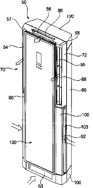
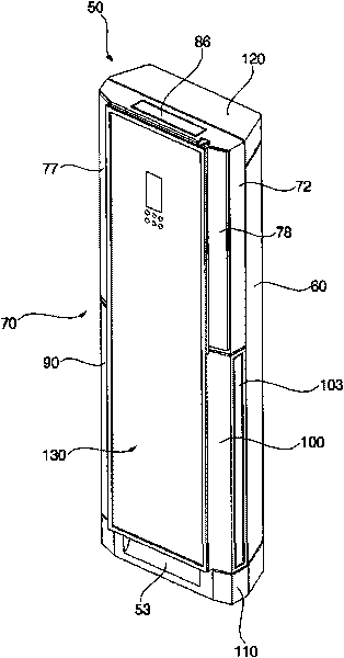
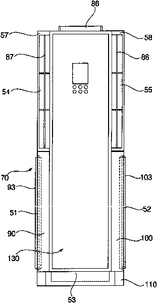
[0050] The present invention will be described in further detail below in conjunction with accompanying drawing and specific embodiment: the working principle of cabinet type air-conditioning indoor unit of the present invention is identical with prior art, can refer to prior art, so no longer describe, the present invention and existing The difference in technology is that the installation structure of the air filter is different, which will be described in detail below, and the same symbols will be used for the same parts as those in the prior art:

[0051] Such as Figure 5 , 6 As shown, in the installation structure of the air filter of the indoor unit of the cabinet type air conditioner of the present invention, the air filter 4 is located at the air outlet above the indoor air supply turbo fan, and a slender and elongated wall is formed on the left side panel 62 along the front and rear directions. Two guide rails 3 are formed between the left side panel 62 and the righ...


PUM


Abstract

The invention discloses a mounting structure of an air filter of a cabinet air-conditioning indoor unit. The air filter is positioned at an airflow outlet above an indoor air supply turbofan. Because the air filter is placed at the outlet of the fan, the suction resistance of the fan is greatly reduced, and the flow is improved; the inlet space of the fan is increased so that the airflow is not accumulated in the inlet space of the fan and the noise is reduced; the airflow at the outlet of the fan nearly flows upwards vertically and is well matched with the crisscross structure of the air filter, so noise is not caused in the inlet space; and when a customer needs to clean the air filter, the filter can be extracted from the lateral surface.

Description

technical field [0001] The invention relates to an air conditioner, in particular to an installation structure of an air filter of an indoor unit of a cabinet type air conditioner. Background technique [0002] Generally, an air conditioner is a machine for cooling or heating indoors and purifying indoor air by using a refrigeration cycle composed of a compressor, a condenser, an expansion component, and an evaporator in order to provide users with a comfortable environment. [0003] Existing cabinet air conditioner indoor units such as Figures 1 to 4 As shown, a body 50 constituting the exterior is included. The lower part of the main body 50 forms air suction ports 51, 52 for sucking indoor air. [0004] The air inlets 51 and 52 include a left side air inlet 51 provided on the lower left side of the main body 50 and a right side air inlet 52 provided on the lower right side of the main body 50 . [0005] The lower front of the main body 50 is also provided with a front ...

Claims


Application Information

Patent Timeline
IPC IPC(8): F24F13/28F24F1/00
Inventor 闫小康
Owner LG ELECTRONICS (TIANJIN) APPLIANCES CO LTD
Why Eureka
Try Eureka