Lpi fuel supply system

a fuel supply system and fuel pump technology, applied in the direction of positive displacement liquid engines, electric control, machines/engines, etc., can solve the problems of weakening the supply capacity of the pump, and achieve the effect of reducing the suction resistance of the fuel pump and improving the supply and suction capacity of the fuel pump

Active Publication Date: 2011-03-03
HYUNDAI MOTOR CO LTD
View PDF13 Cites 5 Cited by
  • Summary
  • Abstract
  • Description
  • Claims
  • Application Information

AI Technical Summary

Benefits of technology

[0021]In the LPI fuel supply system according to various aspects of the present invention, the jet nozzle is disposed in the suction line to reduce the suction resistance of the fuel pump. Accordingly, the supply and the suction capacity of the fuel pump are securely improved in the fuel supply system.

Problems solved by technology

However, when the fuel pump is deteriorated or foreign substances are accumulated in the main filter of the fuel pump, there is a problem that the supply capacity of the pump becomes weakened.

Method used


Image

  • Lpi fuel supply system
  • Lpi fuel supply system
  • Lpi fuel supply system

Examples


Embodiment Construction

[0029]Reference will now be made in detail to various embodiments of the present invention(s), examples of which are illustrated in the accompanying drawings and described below. While the invention(s) will be described in conjunction with exemplary embodiments, it will be understood that present description is not intended to limit the invention(s) to those exemplary embodiments. On the contrary, the invention(s) is / are intended to cover not only the exemplary embodiments, but also various alternatives, modifications, equivalents and other embodiments, which may be included within the spirit and scope of the invention as defined by the appended claims.

[0030]An exemplary embodiment of the present invention will hereinafter be described in detail with reference to the accompanying drawings.

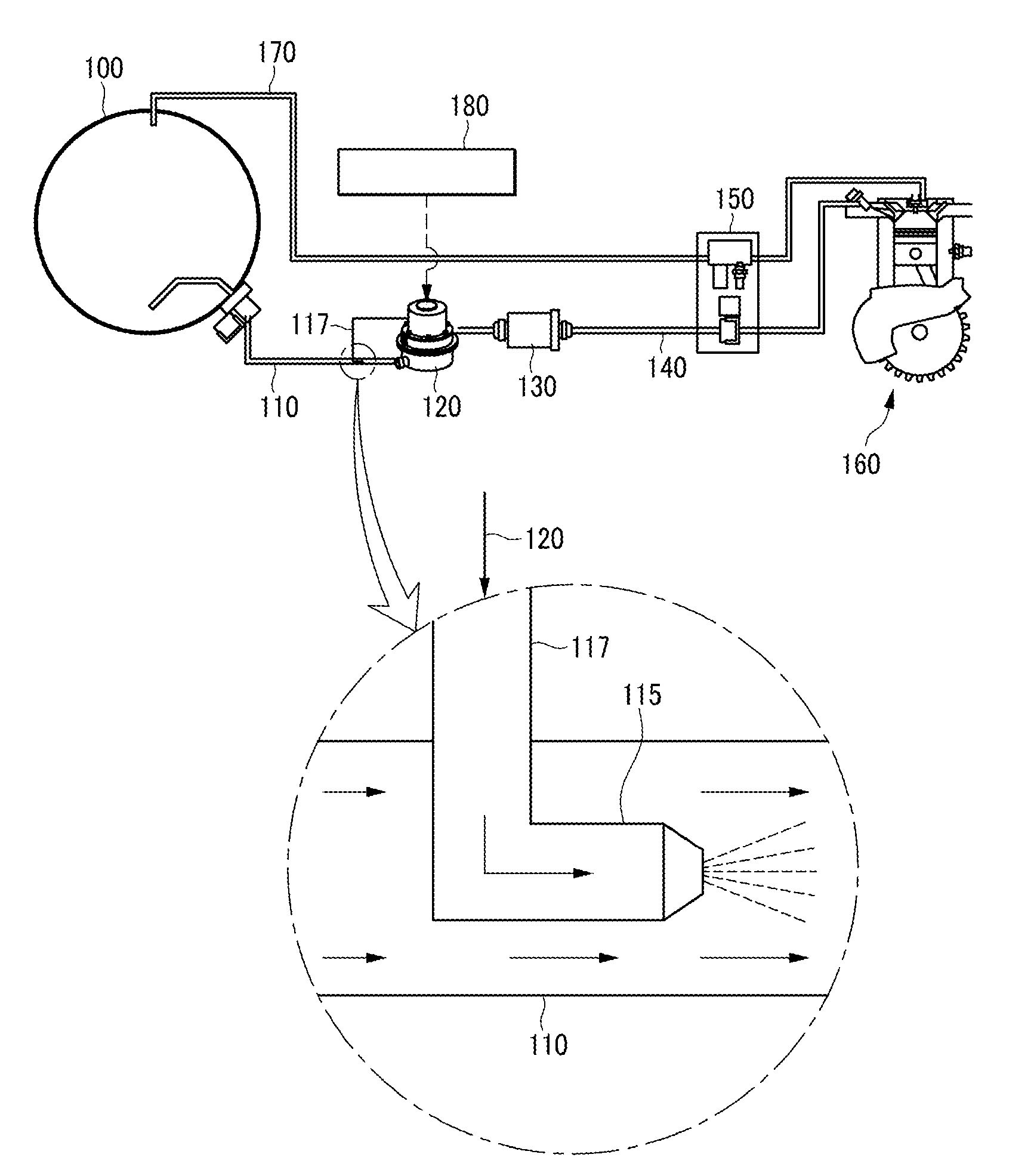
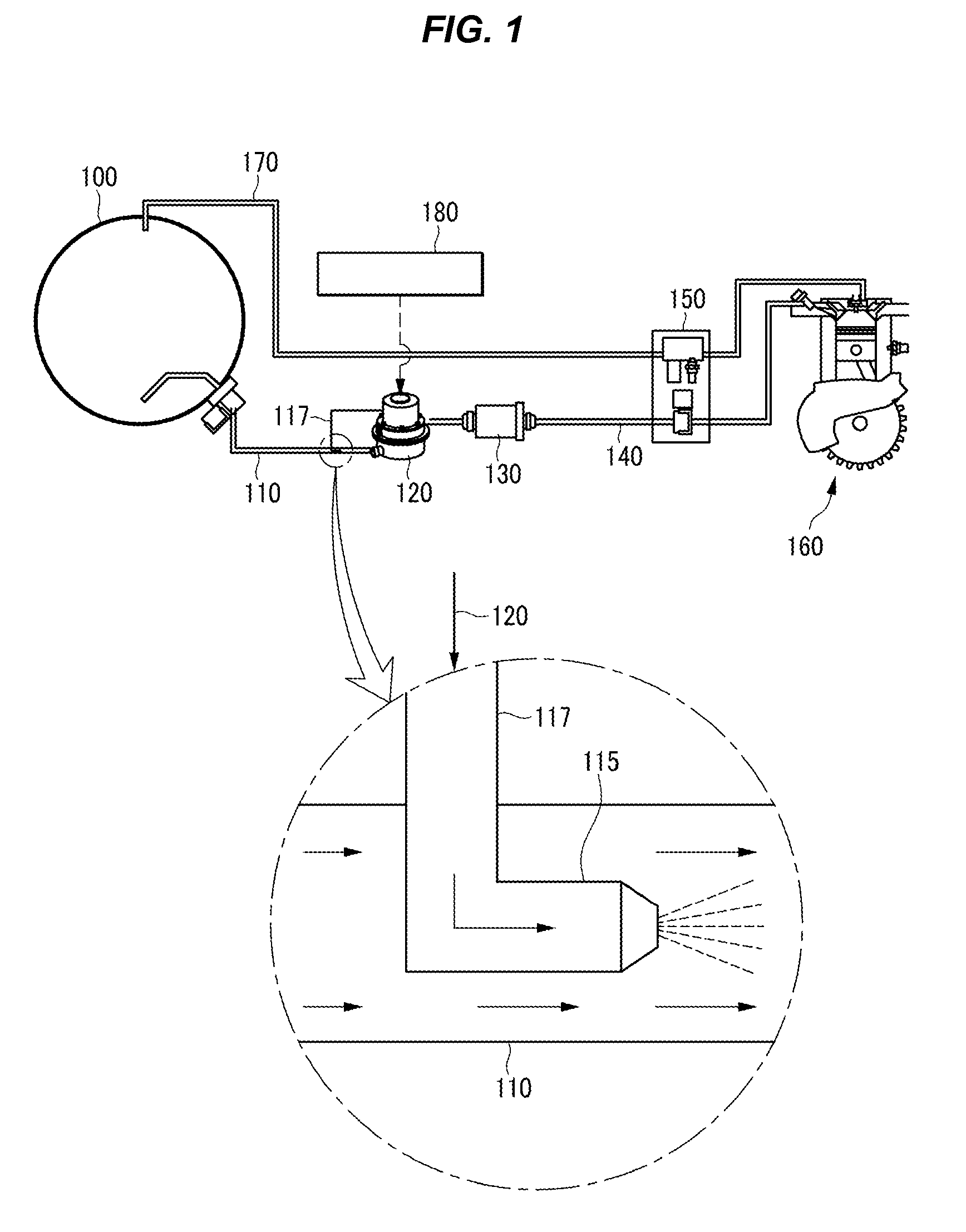
[0031]FIG. 1 is a schematic diagram of an LPI fuel supply system according to an exemplary embodiment of the present invention.

[0032]Referring to FIG. 1, an LPI fuel supply system includes a fuel t...


PUM


Abstract

A fuel supply system may include a fuel tank that is filled with fuel, a fuel pump supplying an engine with the fuel in the fuel tank, a suction line connecting the fuel tank to the fuel pump, a supply line connecting the fuel pump to the engine, and a jet nozzle disposed in the suction line to inject a portion of fuel that is supplied from the fuel pump in a flowing direction of the fuel supplied from the fuel tank.

Description

CROSS-REFERENCE TO RELATED APPLICATION[0001]The present application claims priority to Korean Patent Application No. 10-2009-0079453 filed on Aug. 26, 2009, the entire contents of which are incorporated herein for all purposes by this reference.BACKGROUND OF THE INVENTION[0002]1. Field of the Invention[0003]The present invention relates to an LPI fuel supply system. More particularly, the present invention relates to an LPI fuel supply system that securely supplies an engine with fuel from a fuel tank.[0004]2. Description of Related Art[0005]Generally, a liquefied petroleum injection (LPI) engine uses an injector to inject liquefied fuel into a cylinder.[0006]The operation principle of the LPI engine is schematically explained as follows: an electronic control unit (ECU) receives input signals from sensors to detect the condition of the engine and controls a fuel pump, the injector, and an ignition coil so as to optimize air / fuel ratio and engine performance.[0007]That is, the fuel ...

Claims


Application Information

Patent Timeline
Patent Type & Authority Applications(United States)
IPC IPC(8): F02M69/04
CPCF02D41/32Y02T10/32F02M21/0245F02M21/0212F02M21/0242F02M37/025Y02T10/30F02M21/02F02M37/00F02M37/08
Inventor SONG, JU TAE
Owner HYUNDAI MOTOR CO LTD
Why Eureka
Try Eureka