Opening self-destruction type anti-fake bottle cap
An anti-counterfeiting bottle cap and self-destructing technology, which is applied to the parts of bottles/cans, locking equipment, closing, etc., can solve the problems of destroying the anti-counterfeiting structure, illegal elements recycling and fraudulent elements, and illegal elements unable to recycle and utilize them. Sealing effect, easy to use, and stable structure
- Summary
- Abstract
- Description
- Claims
- Application Information
AI Technical Summary
Problems solved by technology
Method used
Image
Examples
Embodiment 1
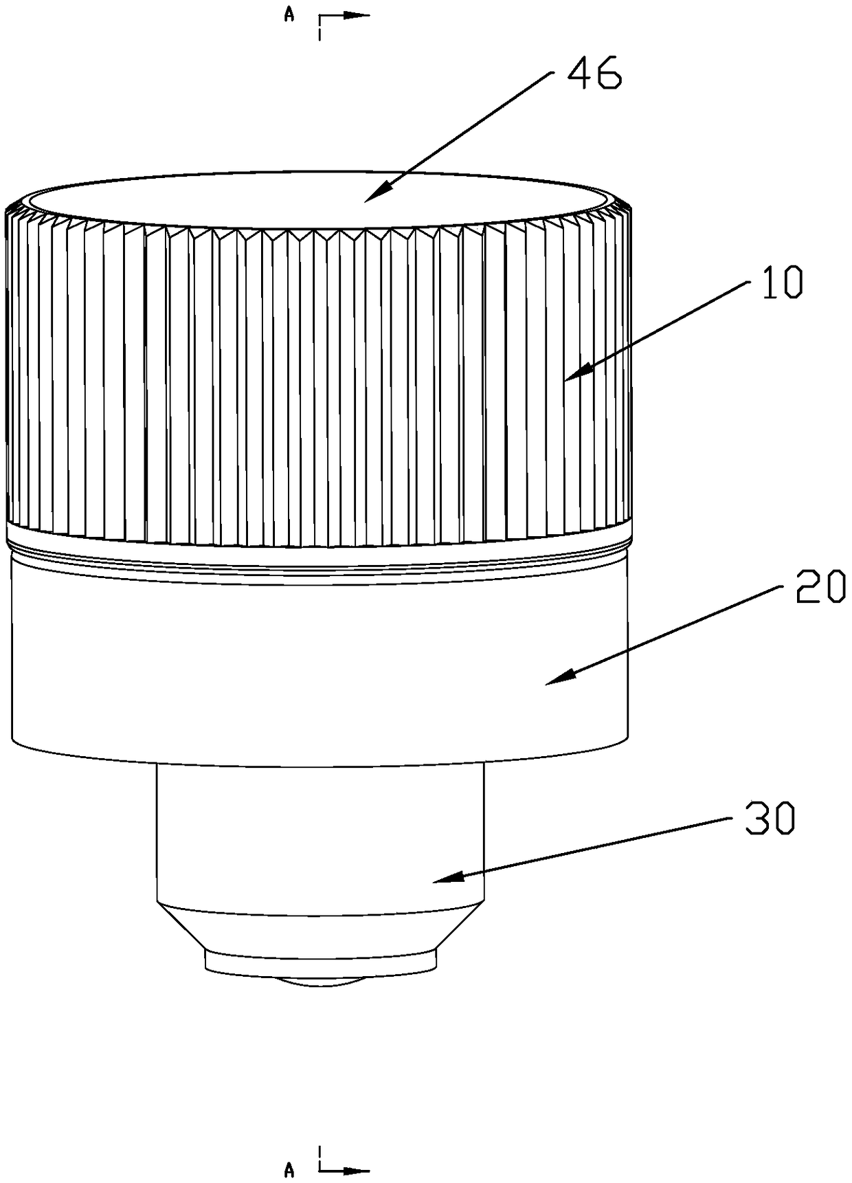
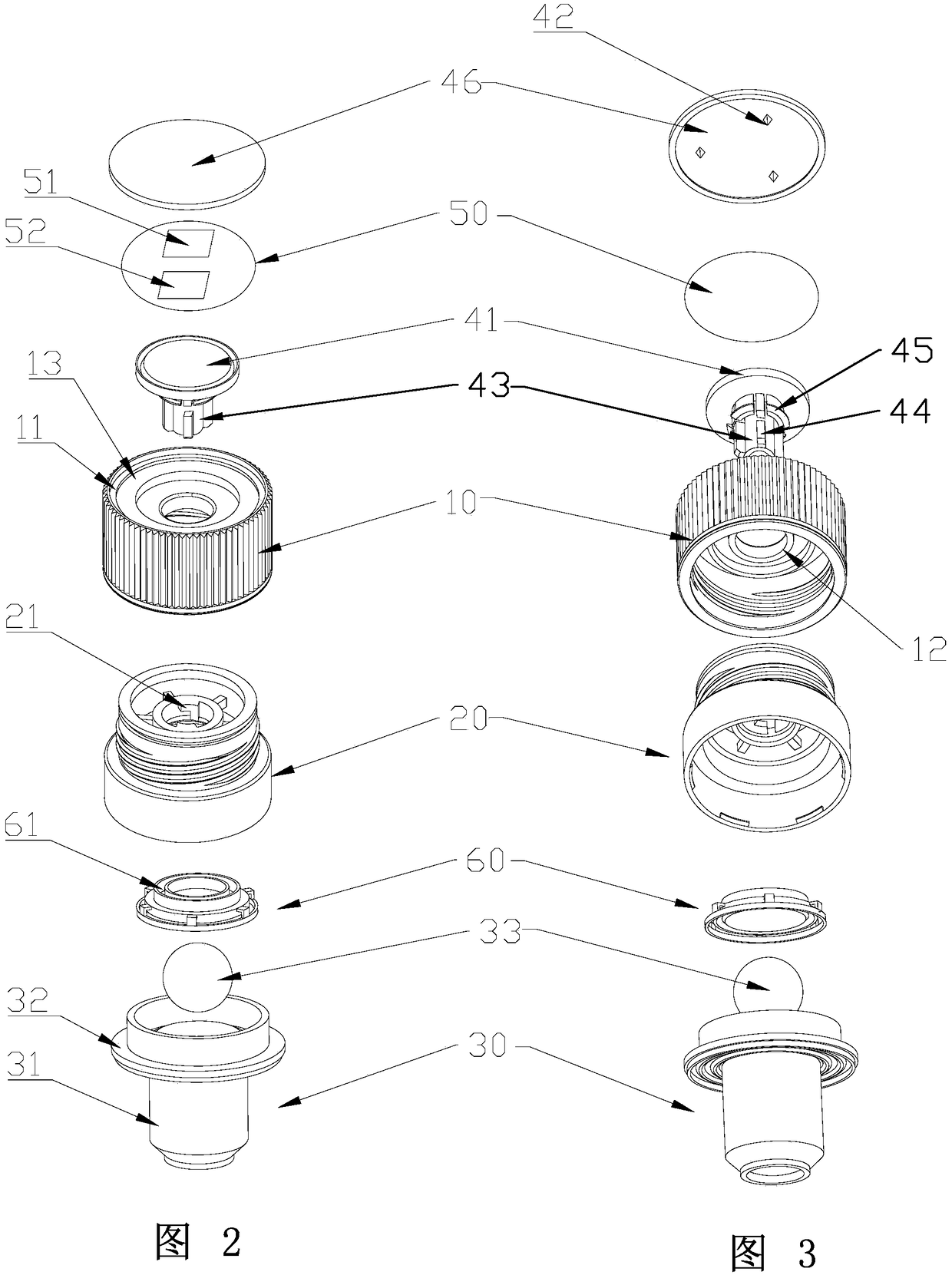
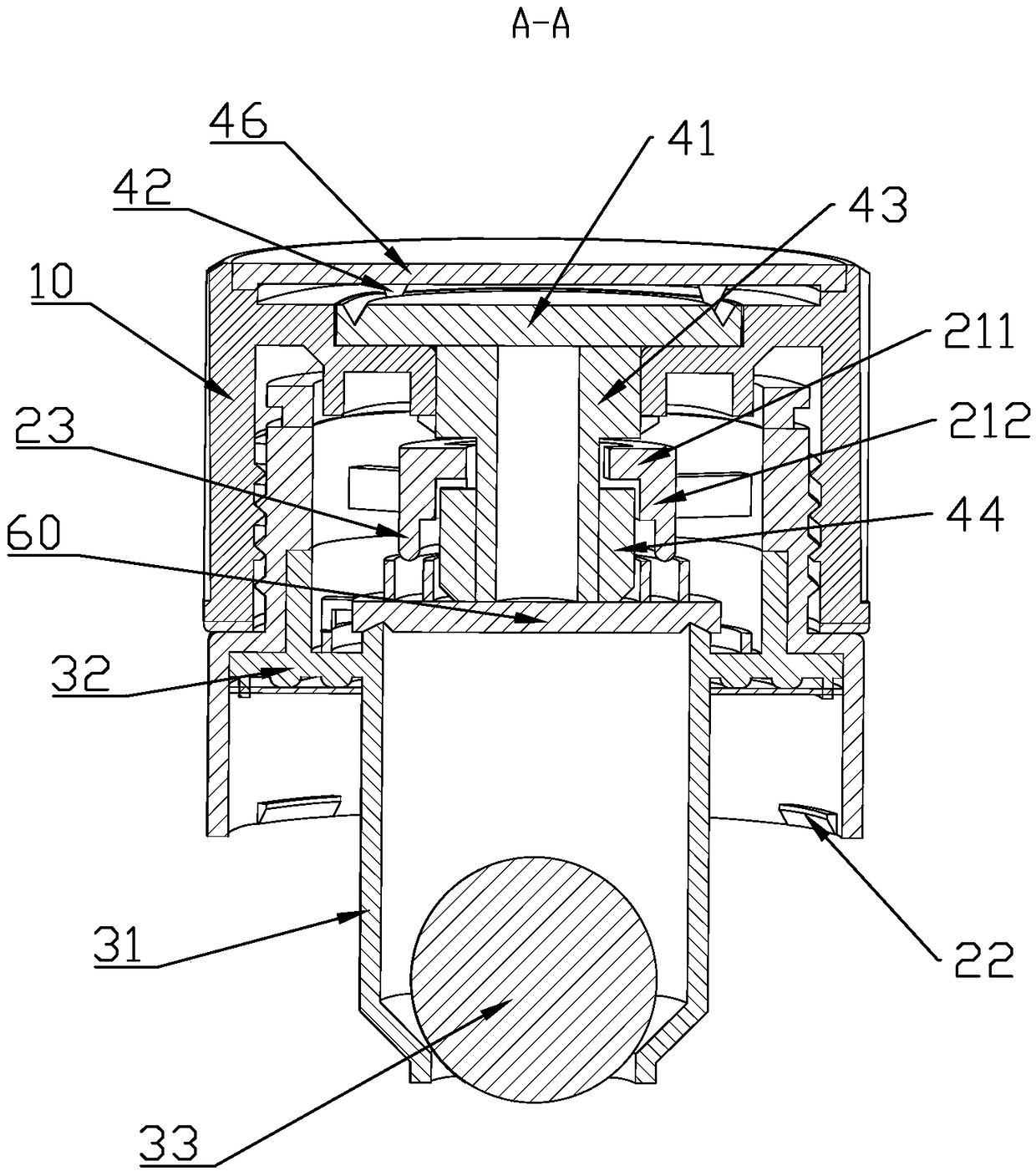
[0032] like Figure 1~4 As shown, the uncapped self-destruct anti-counterfeit bottle cap of the present embodiment includes an upper cover 10 , a lower cover 20 , a self-destruct device 40 and an anti-counterfeit label 50 . The upper cover 10 and the lower cover 20 are flexibly connected. In this embodiment, both the upper cover 10 and the lower cover 20 are circular, the upper cover 10 includes a top wall 11 and side walls, the lower end of the side wall of the upper cover 10 is provided with internal threads, and the upper end of the lower cover 20 is provided with external threads , The upper cover 10 and the lower cover 20 realize the rotational connection through the cooperation of the internal thread and the external thread. The lower end of the lower cover 20 is connected to the mouth of the bottle. Specifically, a buckle 22 is provided on the outer wall of the lower cover 20 to be fixed on the mouth of the bottle through the buckle 22 .
[0033]Both the upper cover 1...
Embodiment 2
[0036] like Figure 3-6 As shown, the present embodiment further defines the lower cover stopper 21 on the basis of the first embodiment. Specifically, the lower cover stopper 21 is composed of a first stopper 211 and a second stopper 212 connected to each other, the first stopper 211 is located above the second stopper 212, and the first stopper 211 and the second stopper 212 An angle is formed between them; the clamping block 44 is engaged at the angle between the first blocking block 211 and the second blocking block 212 . In this embodiment, the first stopper 211 is in the horizontal direction, the second stopper 212 is in the vertical direction, and the second stopper 212 is connected to the right end of the first stopper 211, and the clamping block 44 is engaged in the second The right angle between the first stopper 211 and the second stopper 212 ; and there are two lower cover stoppers 21 , which are evenly arranged on the inner wall of the lower cover 20 . The lengt...
Embodiment 3
[0039] like Figure 3-5 As shown, the present embodiment adds an annular boss 45 on the basis of Embodiment 2. Specifically, the outer wall of the fixing column 43 is provided with an annular boss 45, and the inner wall of the upper cover 10 is provided with a downward upper cover. The clamping block 12 and the upper cover clamping block 12 are located above the boss 45, so that the lower end of the upper cover clamping block 12 and the upper surface of the boss 45 interfere with each other. In this embodiment, the upper cover block 12 is also ring-shaped, and the upper cover block 12 and the upper cover 10 are integrally formed. By setting the annular boss 45 , on the one hand, it is convenient for the upper cover 10 to rotate around the self-destruct device 40 ;
PUM
 Abstract
Description
Claims
Application Information
 - R&D
- Intellectual Property
- Life Sciences
- Materials
- Tech Scout
- Unparalleled Data Quality
- Higher Quality Content
- 60% Fewer Hallucinations
Browse by: Latest US Patents, China's latest patents, Technical Efficacy Thesaurus, Application Domain, Technology Topic, Popular Technical Reports.
© 2025 PatSnap. All rights reserved.Legal|Privacy policy|Modern Slavery Act Transparency Statement|Sitemap|About US| Contact US: help@patsnap.com


