
Stator blade regulating mechanism of air compressor

A technology of regulating mechanism and compressor, applied in the direction of machine/engine, mechanical equipment, engine components, etc., can solve the problems of optimization, unable to realize the force transmission efficiency of the mechanism at the same time, and the difference in the angle and range of the adjustment cannot be too large.

Active Publication Date: 2019-03-22
AECC COMML AIRCRAFT ENGINE CO LTD
View PDF6 Cites 3 Cited by
  • Summary
  • Abstract
  • Description
  • Claims
  • Application Information

AI Technical Summary

Problems solved by technology

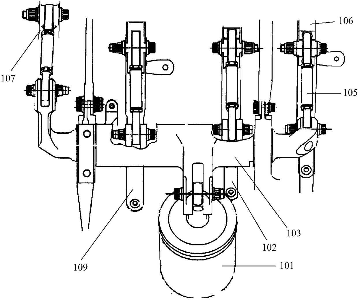
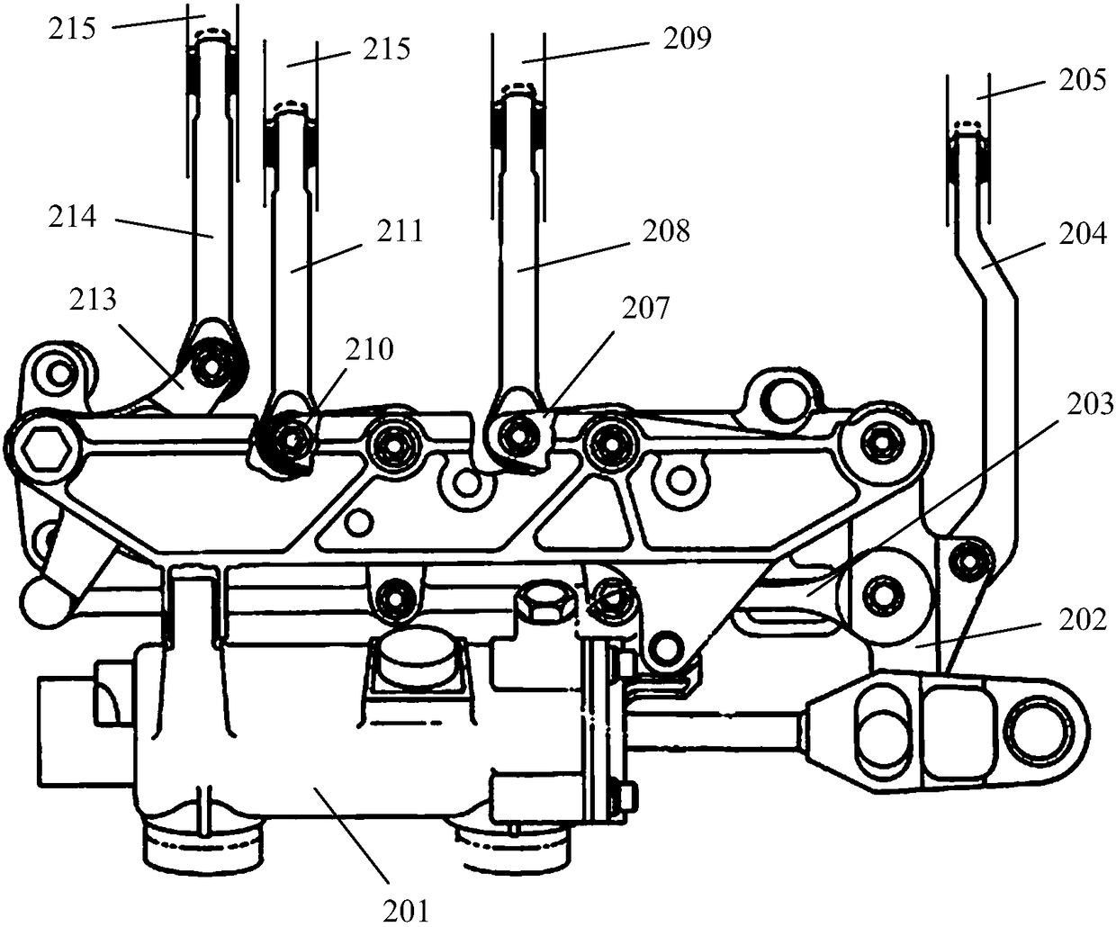
In these two configurations, the rotation angles of the driving driven ends of the torsion bar (103) and the cranks (202, 207, 210, 213) of each stage are the same, which can only be determined by the length of the driven end of the torsion bar or the crank and the length of the driven end of the crank. Its initial angle and other parameters are adapted to the different adjustment angles and ranges of the stator blades at all levels. In this case, in order to ensure the movement position, it is impossible to optimize the force transmission efficiency of the mechanism at the same time, and at the same time limit the adjustable stator blades at all levels. The difference in the angle and range of adjustment should not be too large

Method used


Image

  • Stator blade regulating mechanism of air compressor
  • Stator blade regulating mechanism of air compressor
  • Stator blade regulating mechanism of air compressor

Examples


Embodiment Construction

[0018] The present invention will be further described below in conjunction with specific embodiment and accompanying drawing, set forth more details in the following description so as to fully understand the present invention, but the present invention can obviously be implemented in many other ways different from this description, Those skilled in the art can make similar promotions and deductions based on actual application situations without violating the connotation of the present invention, so the content of this specific embodiment should not limit the protection scope of the present invention.

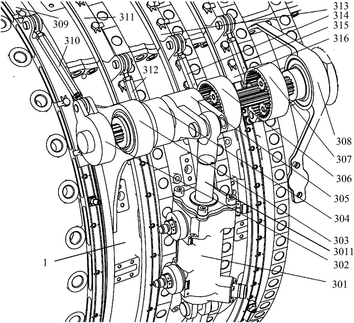
[0019] have to be aware of is, image 3 and Figure 4 Showing one embodiment of the invention, these and other drawings that follow are by way of example only, are not drawn to scale, and should not be construed as limiting the actual claimed scope of the invention.

[0020] In the following embodiments, the linkage relationship between the stages of the multi-stage linkage ri...


PUM


Abstract

The invention provides a stator blade regulating mechanism of an air compressor. The stationary blade regulating mechanism satisfies the requirements of an aerodynamic design and the requirements thatthe regulation angles and ranges of different stator blades have relatively large differences. The stator blade regulating mechanism comprises a driving part, a simultaneous driving shaft, a multi-stage link assembly, a multi-stage linkage ring component and a multi-stage driving end component, wherein the driving part is used for outputting motion; the simultaneous driving part is driven by thedriving part and is used for outputting rotation; the driving end component acting in each stage of the multi-stage driving end component comprises a plurality of switching gears and driving bodies; the simultaneous driving shaft is used for providing gear shaft parts corresponding to the driving end components acting in all stages; the gear shaft parts and the corresponding driving end componentsacting in all stages together form a planet gear system; in the planet gear system, each gear shaft part is set as a sun gear; the plurality of switching gears are set as planet gears; each driving body is used for providing an inner gear; and the multi-stage link component and the multi-stage linkage ring component respectively correspond to the multi-stage driving end component and are in transmission connection with the multi-stage driving end component.

Description

technical field [0001] The invention relates to an adjustment mechanism of a stator vane of a compressor. Background technique [0002] Adjustable vanes can be used to improve the stable working range of the compressor, and are widely used in aero-engines. Generally, there are multi-stage adjustable vanes in the compressor. In order to realize the joint adjustment of each stage at different state points, it is necessary to design a set of adjustment mechanisms. The existing designs mainly include two types, one is torsion bar adjustable vane adjustment bodies, such as the GE90 series, such as figure 1 As shown, the actuator (101) drives the torsion bar (103) to rotate, and the driving end and the driven end on the torsion bar (103) rotate at the same time and at the same angle, and drive the connecting rod assemblies (105) at all levels to rotate simultaneously to realize Linkage ring components (102, 106, 107, 109) at all levels are linked; the second is the crank-link ty...

Claims


Application Information

Patent Timeline
Patent Type & Authority Applications(China)
IPC IPC(8): F01D17/20F04D29/56
CPCF01D17/20F04D29/563
Inventor 林清松曹艺郭绍唱聂聪
Owner AECC COMML AIRCRAFT ENGINE CO LTD
Learn More