
Overload clutch for speed reducer

An overload clutch and clutch technology, applied in the field of clutches, can solve the problems such as the safety of the binding device cannot be effectively guaranteed, the overload clutch slips, the system efficiency is reduced, etc., and achieves the effects of preventing slippage, improving life, and simple processing technology.

Inactive Publication Date: 2019-03-22
SHAANXI UNIV OF SCI & TECH
View PDF8 Cites 0 Cited by
  • Summary
  • Abstract
  • Description
  • Claims
  • Application Information

AI Technical Summary

Problems solved by technology

[0002] The general overload clutch is prone to slipping, and the structural design is relatively complicated. Once the overload clutch in the tensioning device slips, the efficiency of the entire system will be greatly reduced, and the safety of the binding device will not be effectively guaranteed.

Method used


Image

  • Overload clutch for speed reducer
  • Overload clutch for speed reducer

Examples


Embodiment Construction

[0012] The present invention is further described below in conjunction with the accompanying drawings.

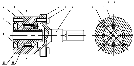
[0013] like figure 1 As shown, an overload clutch for a reducer includes a shaft 8, the shaft 8 penetrates the clutch housing 7, the sleeve shaft 3 is sleeved on the shaft 8, and withstands the clutch housing 7. The clutch housing 7 is divided into two parts and is fixed by screws 4. A plug 2 is installed on the casing 7, the inner cavity of the clutch casing 7 supports the shaft 8 through a bearing 10, a retaining ring 9 is arranged at the rear end of the bearing 10, a spacer 11 is arranged between the bearings 10, and a spacer 11 is arranged between the bearing 10 and the spacer 11. There is a stopper block 1, and a spring is installed on the stopper block 1.

[0014] A stop washer is provided between the screw 4 and the clutch housing 7 .

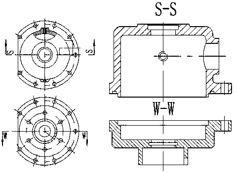
[0015] like figure 2 As shown, the clutch housing 7 may be provided with a protective cover.

[0016] The working principle of ...


PUM


Abstract

The invention discloses an overload clutch for a speed reducer. The overload clutch comprises a shaft, wherein the shaft penetrates through a clutch housing; a sleeve shaft is arranged on the shaft ina sleeving manner and jacks the clutch housing; the clutch housing is divided into two parts and is fixed through a screw; a plug is mounted on the clutch housing; the cavity of the clutch housing penetrates through a bearing support shaft; a retainer ring is arranged at the rear end of each of bearings; a space ring is arranged between the bearings; a stop block is arranged between each of the bearings and the space ring; a spring is mounted on the stop block; the stop blocks are mounted between the springs to play a fixing role during the operation process of the bearings; the plug is mounted on the clutch housing to plug a pipe opening not used so as to play a sealing role; the sleeve shaft is mounted on the shaft to reduce abrasion during the operating process of the shaft; the retainer ring is used for limiting; the bearings support the shaft to reduce the friction coefficient during the rotary motion process and ensure the rotary precision; the space ring is used for keeping theaxial distance of the bearings, is simple in processing technology and convenient to mount and dismantle and can prevent the overload clutch from slipping to prolong the service life of an entire fastening system.

Description

technical field [0001] The invention belongs to the technical field of clutches, and in particular relates to an overload clutch for a reducer. Background technique [0002] The general overload clutch is prone to slip phenomenon, and the structure design is relatively complicated. Once the overload clutch in the tensioning device slips, the efficiency of the entire system is greatly reduced, and the safety of the binding device cannot be effectively guaranteed. SUMMARY OF THE INVENTION [0003] In order to overcome the above-mentioned deficiencies of the prior art, the purpose of the present invention is to provide an overload clutch for a reducer, which can effectively prevent the overload clutch from slipping. [0004] In order to achieve the above object, the technical scheme adopted in the present invention is: [0005] An overload clutch for a reducer comprises a shaft, the shaft penetrates a clutch casing, a sleeve shaft is sleeved on the shaft, and withstands the ...

Claims


Application Information

Patent Timeline
IPC IPC(8): F16D43/20
CPCF16D43/20
Inventor 栾飞芦文婷徐家悦田帅博桓源荆礼王桯魏引焕
Owner SHAANXI UNIV OF SCI & TECH
Learn More