Heat-resistant structures for kiln cars in tunnel kilns
What is Al technical title?
Al technical title is built by PatSnap Al team. It summarizes the technical point description of the patent document.
A technology of tunnel kiln and kiln car is applied in the field of heat-resistant structure of tunnel kiln car, which can solve the problems of high price of refractory bricks, easy breakage and falling, and high investment in new brick and tile factories.
Active Publication Date: 2020-10-30
武汉四海大通自动化设备有限公司
View PDF6 Cites 0 Cited by
Summary
Abstract
Description
Claims
Application Information
AI Technical Summary
This helps you quickly interpret patents by identifying the three key elements:
Problems solved by technology
Method used
Benefits of technology
Problems solved by technology
[0002] The existing kiln car is covered with refractory bricks on the kiln car. The refractory bricks are directly placed on the kiln car and exposed outside the kiln car. They are easy to break and fall off. Brick and tile factories spend a lot of money on repairs every year, and the price of refractory bricks is high. , high investment in new brick and tile factories
Method used
Image
Click on the blue label to locate the original text in one second.
Reading with bidirectional positioning of images and text.
Examples
Embodiment Construction
[0039] The implementation of the present invention will be described in detail below in conjunction with the accompanying drawings, but they do not constitute a limitation to the present invention, and are only examples. At the same time, the advantages of the present invention will become clearer and easier to understand through the description.
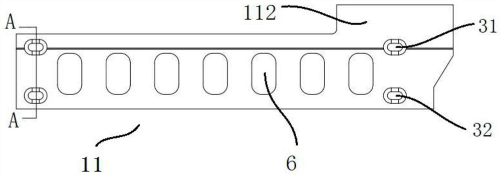
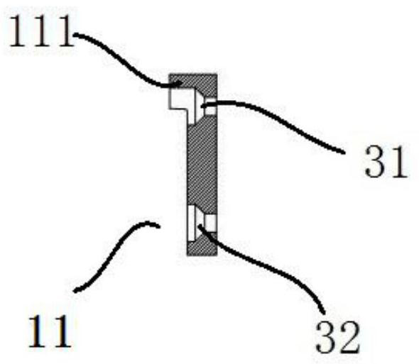
[0040] Referring to the accompanying drawings, it can be known that the heat-resistant structure used for the kiln car of the tunnel kiln includes the convex coaming plate 11 and the concave coaming plate 12 installed on the left and right sides of the kiln car 7, and is installed on the left and right sides of the kiln car 7 and located on the convex coaming plate 11. and the side wall 4 between the concave wall 12, the front wall 21 installed on the front side of the kiln car 7, and the rear wall 22 installed on the rear side of the kiln car 7; the convex wall 11 and the side wall 4 between the concave wall 12 and the side wall 4 ...
PUM
Abstract
The invention discloses a heat-resistant structure for a tunnel kiln car, and relates to a kiln car heat-resistant structure. The heat-resistant structure comprises a convex coaming plate, a concave coaming plate, side coaming plates, front coaming plates and back coaming plates; the convex coaming plate and the side coaming plates are connected through coaming plate channel steel, the concave coaming plate and the side coaming plates are connected through coaming plate channel steel, and the coaming plate channel steel is fixed to a frame of the kiln car; a convex coaming plate convex plate is arranged at the upper end of the face, far away from the kiln car, of the convex coaming plate, and a concave coaming plate convex plate is arranged at the upper end of the face, close to the kiln car, of the concave coaming plate; side coaming plate convex plates are arranged at the upper ends of the faces, far away from the kiln car, of the side coaming plate; front coaming plate convex platesare arranged at the upper ends of the faces, far away from the kiln car, of the front coaming plates, and back coaming plate convex plates are arranged at the lower ends of the faces, far away from the kiln car, of the back coaming plates; and heat-resistant cotton, earth and red bricks are sequentially laid on the upper surface of the kiln car from bottom to top. According to the heat-resistantstructure for the tunnel kiln car, the service life of the kiln car is significantly prolonged, the manufacture cost and the maintenance cost of the kiln car are significantly reduced, refractory bricks are replaced with the earth and the red bricks, and almost no maintenance cost is generated.
Description
technical field [0001] The invention relates to a heat-resistant structure of a kiln car, more specifically it is a heat-resistant structure for a tunnel kiln car. Background technique [0002] The existing kiln car is covered with refractory bricks on the kiln car. The refractory bricks are directly placed on the kiln car and exposed outside the kiln car. They are easy to break and fall off. Brick and tile factories spend a lot of money on repairs every year, and the price of refractory bricks is high. , The investment in new brick and tile factories is high. [0003] Therefore, developing a heat-resistant structure for tunnel kiln cars has become an urgent and important task. Contents of the invention [0004] The object of the present invention is to provide a heat-resistant structure for a tunnel kiln car in order to overcome the disadvantages of the above-mentioned background technology. [0005] In order to achieve the above object, the technical solution of the pr...
Claims
Application Information
Patent Timeline
Application Date:The date an application was filed.
Publication Date:The date a patent or application was officially published.
First Publication Date:The earliest publication date of a patent with the same application number.
Issue Date:Publication date of the patent grant document.
PCT Entry Date:The Entry date of PCT National Phase.
Estimated Expiry Date:The statutory expiry date of a patent right according to the Patent Law, and it is the longest term of protection that the patent right can achieve without the termination of the patent right due to other reasons(Term extension factor has been taken into account ).
Invalid Date:Actual expiry date is based on effective date or publication date of legal transaction data of invalid patent.