Eureka AIR delivers breakthrough ideas for toughest innovation challenges, trusted by R&D personnel around the world.

Ultrasonic flow measuring method and low-power-consumption ultrasonic flow meter

A flow measurement and ultrasonic technology, applied in the field of flow detection, can solve the problems of low performance, low accuracy, limited application, etc., to achieve the effect of improving stability and accuracy, less external interference, and strong robustness

Pending Publication Date: 2019-03-22
XIAN ANCN INTELLIGENT INSTR
View PDF6 Cites 10 Cited by
  • Summary
  • Abstract
  • Description
  • Claims
  • Application Information

AI Technical Summary

Problems solved by technology

[0002] At present, there are many domestic ultrasonic flowmeter products with low cost, but the overall performance is not high. Foreign ultrasonic flowmeters are better in terms of accuracy and performance, but they are expensive, which limits their large-scale application in industry.
[0003] Ultrasonic flowmeters are mostly measured using the time difference method, and time measurement is mostly based on threshold zero-crossing comparison or cross-correlation algorithm. Threshold zero-crossing comparison has relatively high requirements for the stability and consistency of ultrasonic sensors, and the ultrasonic echo signal must be stable. But at present, the performance of domestic ultrasonic sensors is not particularly good. The performance of foreign sensors is good, but the price is too expensive, which is several times that of domestic sensors.
The cross-correlation algorithm requires a high-speed ADC, and the flow rate is proportional to the forward and reverse flow time difference. In order to obtain high-precision flow measurement, the forward and reverse flow propagation time difference must be measured with high precision. If the time measurement error is 20ns, the sampling rate of the ADC must reach 50MHz. At present, there is no ADC with such a high sampling rate on the market, so the error of flow measurement using this algorithm will be large and the accuracy will be low

Method used


Image

  • Ultrasonic flow measuring method and low-power-consumption ultrasonic flow meter

Examples


Embodiment Construction

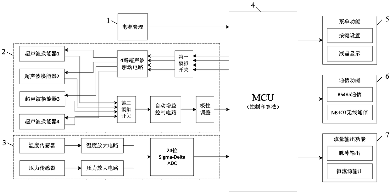
[0043] The present invention firstly proposes an ultrasonic flow measurement method: the method is to use the operation and processing capability of the MCU module to measure the flow with the ultrasonic signal as the object. , upstream time difference, and the absolute flight time in the downstream direction and upstream direction, in order to obtain three time parameters, the algorithm is specifically as follows: taking the downstream and upstream ultrasonic echo signals as input, using cross-correlation and three-parameter fitting sinusoidal curve algorithm , the output obtained by the calculation is the time difference of ultrasonic propagation in the downstream and upstream directions, taking the ultrasonic echo in the downstream direction and the static ultrasonic echo signal under zero flow as input, using the cross-correlation and three-parameter fitting sinusoidal algorithm, the calculation is The output is the absolute flight time in the downstream direction. The abso...


PUM


Abstract

The invention discloses an ultrasonic flow measuring method and a low-power-consumption ultrasonic flow meter. The flow meter comprises an MCU module, a power management module, an ultrasonic wave transmitting and receiving module, a temperature and pressure collecting module, a menu function module, a communication function module and a flow output function module, wherein the power management module, the ultrasonic wave transmitting and receiving module, the temperature and pressure collecting module, the menu function module, the communication function module and the flow output function module are connected with the MCU module separately; the ultrasonic wave transmitting and receiving module comprises two pairs of ultrasonic transducers, a first analog switch, a four-way ultrasonic driving circuit, a second analog switch, an automatic gain control circuit and a polarity adjusting circuit. The flow meter has the advantages of high stability and strong robustness, the noise interference resistance is high, the measurement error can be reduced, the measurement stability and precision of the existing ultrasonic flow meter are obviously improved, and in the production process of a gas field, the volume flow of natural gas can be measured reliably, stably and accurately.

Description

technical field [0001] The invention belongs to the technical field of flow detection and relates to ultrasonic flow measurement, in particular to an ultrasonic flow measurement method and a low-power ultrasonic flowmeter. Background technique [0002] At present, there are many domestic ultrasonic flowmeter products with low cost, but the overall performance is not high. Foreign ultrasonic flowmeters are better in terms of accuracy and performance, but they are expensive, which limits their large-scale application in industry. [0003] Ultrasonic flowmeters are mostly measured using the time difference method, and time measurement is mostly based on threshold zero-crossing comparison or cross-correlation algorithm. Threshold zero-crossing comparison has relatively high requirements for the stability and consistency of ultrasonic sensors, and the ultrasonic echo signal must be stable. But at present, the performance of domestic ultrasonic sensors is not particularly good. Th...

Claims


Application Information

Patent Timeline
Patent Type & Authority Applications(China)
IPC IPC(8): G01F1/66
CPCG01F1/66G01F1/662
Inventor 王士兴胡香儒田冬
Owner XIAN ANCN INTELLIGENT INSTR
Why Eureka
Eureka Blog
Learn More