
Equipment cabin of radiation imaging system and radiation imaging systems

A radiation imaging and equipment cabin technology, applied in the field of radiation imaging systems, can solve the problems of high labor intensity and low efficiency, and achieve the effects of low labor intensity, high efficiency and convenient adjustment

Pending Publication Date: 2019-03-22
许昌瑞示电子科技有限公司
View PDF0 Cites 2 Cited by
  • Summary
  • Abstract
  • Description
  • Claims
  • Application Information

AI Technical Summary

Problems solved by technology

[0004] The purpose of the present invention is to provide a radiation imaging system to solve the problems of low efficiency and high labor intensity in the existing radiation system when aligning the beam output slit of the radiation source, collimator and detector arm

Method used


Image

  • Equipment cabin of radiation imaging system and radiation imaging systems
  • Equipment cabin of radiation imaging system and radiation imaging systems
  • Equipment cabin of radiation imaging system and radiation imaging systems

Examples


Embodiment Construction

[0032] Embodiments of the present invention will be further described below in conjunction with the accompanying drawings.

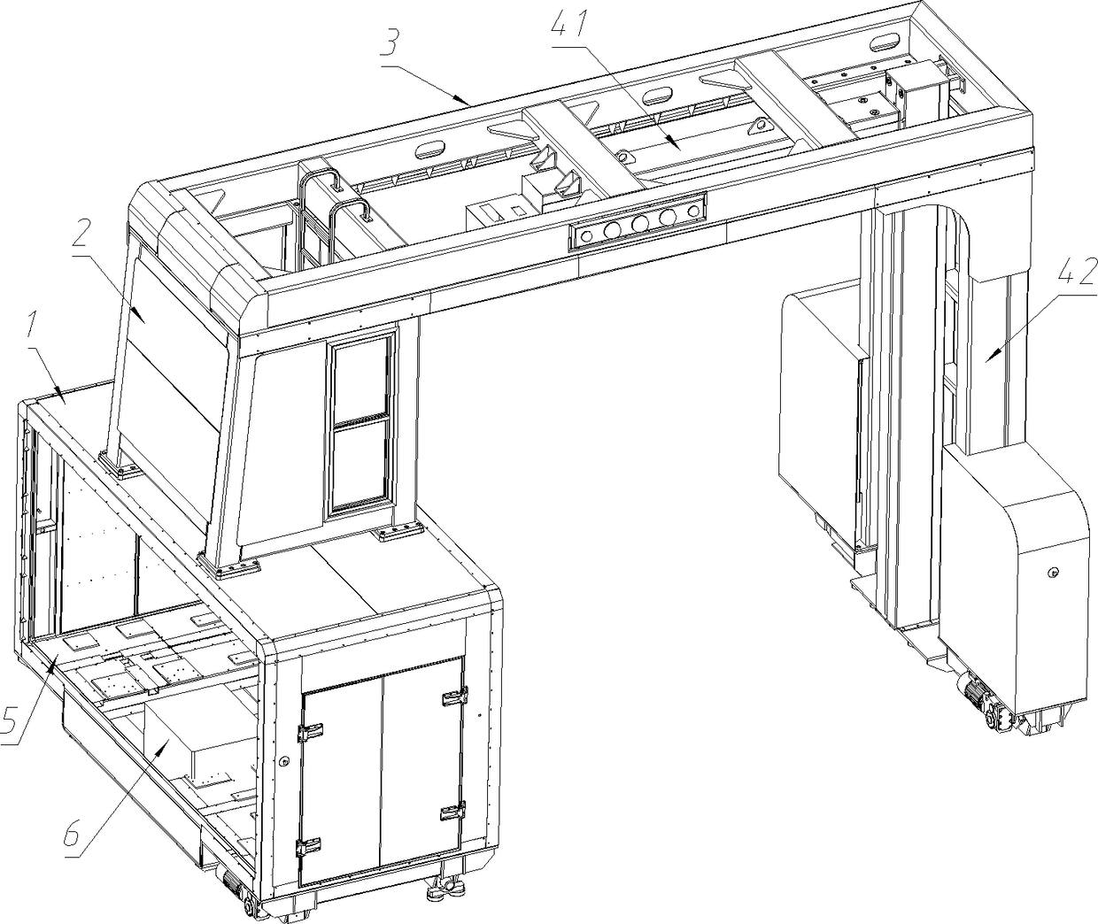
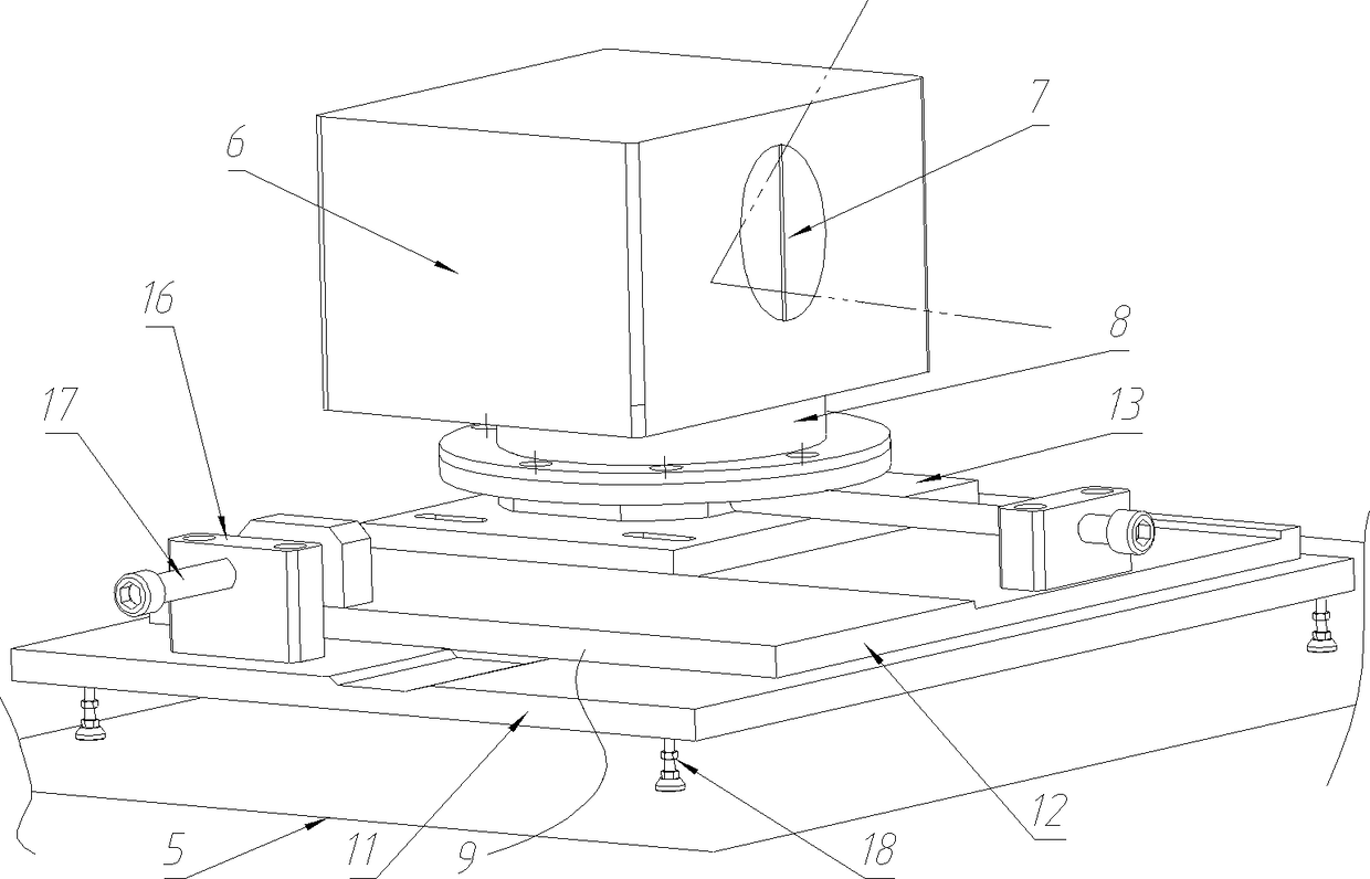
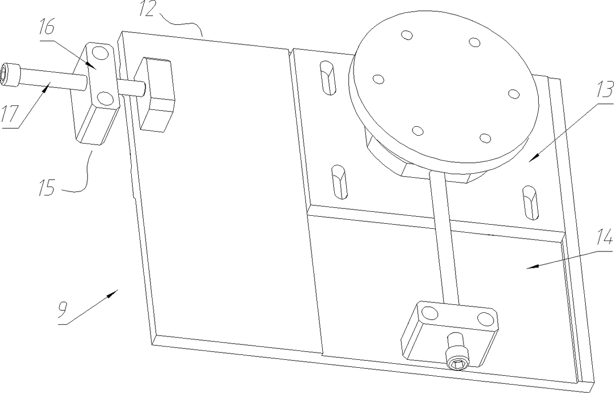
[0033] Specific embodiment one of the radiation imaging system of the present invention, such as figure 1 As shown, the main components of the radiation imaging system include a lower equipment cabin 1 , an upper equipment cabin 2 , a beam 3 , a horizontal detection arm 41 and a vertical detection arm 42 . The horizontal detection arm 41 and the vertical detection arm 42 are provided with detectors, and the lower equipment compartment 1 is provided with a collimator. Wherein the structure and installation method of the upper equipment compartment 2, the crossbeam 3, the horizontal detection arm 41 and the vertical detection arm 42 are all prior art, except that the illustrated structure, it can also adopt any other prior art, not here I will repeat.

[0034]The lower equipment cabin 1 includes a cabin body 5, a radiation source is installed on the bott...


PUM


Abstract

This invention relates to radiation imaging systems, in particular to an equipment cabin of a radiation imaging system. The radiation imaging system comprises the equipment cabin equipped with a radiation source, and further comprises a collimator and a detector; an alignment and adjustment device which is used for adjusting the position of the radiation source to ensure that the radiation sourceis aligned with the collimator and the detector is arranged between the radiation source and the cabin body of the equipment cabin; the alignment and adjustment device comprises a translation supportdevice and legs for supporting the translation support device, the detector or correspondingly arranged leg connection seats; the heights of the support legs are adjustable; the alignment and adjustment device further comprises a rotary structure, a rotating axis of which extends along the vertical direction; and the translation support device, the legs and the rotary structure are layered in an arbitrary order along the vertical direction. Through the alignment and adjustment device, the radiation source can be adjusted to meet the alignment requirement, so that the adjustment is more convenient, and the system has the advantages of being high in efficiency and low in labor intensity.

Description

technical field [0001] The invention relates to a radiation imaging system, in particular to an equipment cabin of the radiation imaging system and the radiation imaging system. Background technique [0002] Radiation imaging system is an important equipment to improve the efficiency of customs inspection. Its main components include radiation sources installed in the equipment cabin (such as natural radioactive cobalt sources, electron accelerator radiation sources, etc.), collimators corresponding to radiation sources, and detector arrays (detector arms). The rays emitted from the beam output slit of the radiation source are processed through the collimator slit on it, so that the rays are aligned with the detector array according to the set path and angle. When in use, the object to be inspected passes through the channel surrounded by the radiation source and the detector array. The radiation source emits rays that can penetrate the object to be inspected. The detector ...

Claims


Application Information

Patent Timeline
IPC IPC(8): G01N23/04G01V5/00F16M13/02F16M11/12
CPCF16M11/12F16M13/02G01N23/04G01V5/22
Inventor 王满仓毛宗钦王骞沈益民
Owner 许昌瑞示电子科技有限公司
Learn More