
Flow control method, switch chip and network device

A technology for switching chips and network equipment, applied in data switching networks, digital transmission systems, electrical components, etc., to solve problems such as CPU crashes and increased CPU load

Active Publication Date: 2019-03-22
RUIJIE NETWORKS CO LTD
View PDF3 Cites 12 Cited by
  • Summary
  • Abstract
  • Description
  • Claims
  • Application Information

AI Technical Summary

Problems solved by technology

However, the existing method of uploading protocol packets to the CPU may increase the load on the CPU and cause the CPU to crash

Method used


Image

  • Flow control method, switch chip and network device
  • Flow control method, switch chip and network device
  • Flow control method, switch chip and network device

Examples


Embodiment Construction

[0018] In order to make the purpose, technical solution and advantages of the present application clearer, the technical solution of the present application will be clearly and completely described below in conjunction with specific embodiments of the present application and corresponding drawings. Apparently, the described embodiments are only some of the embodiments of the present application, rather than all the embodiments. Based on the embodiments in this application, all other embodiments obtained by persons of ordinary skill in the art without making creative efforts belong to the scope of protection of this application.

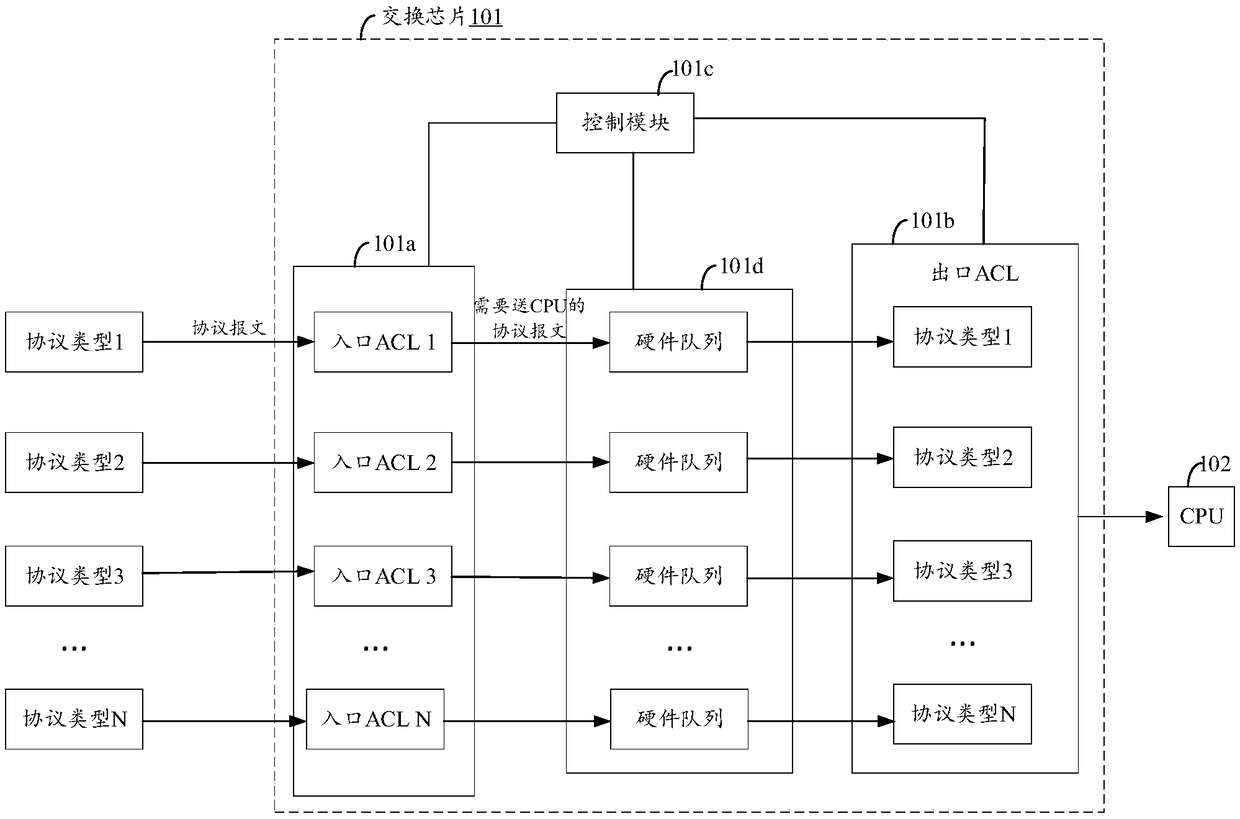
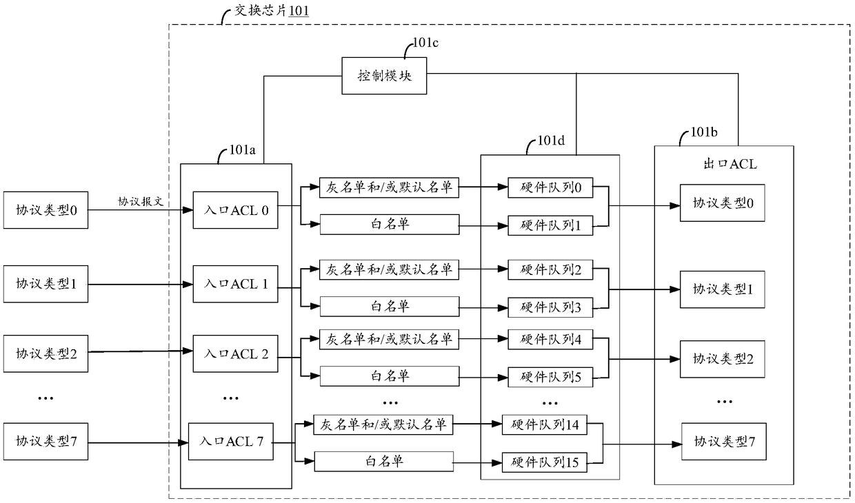
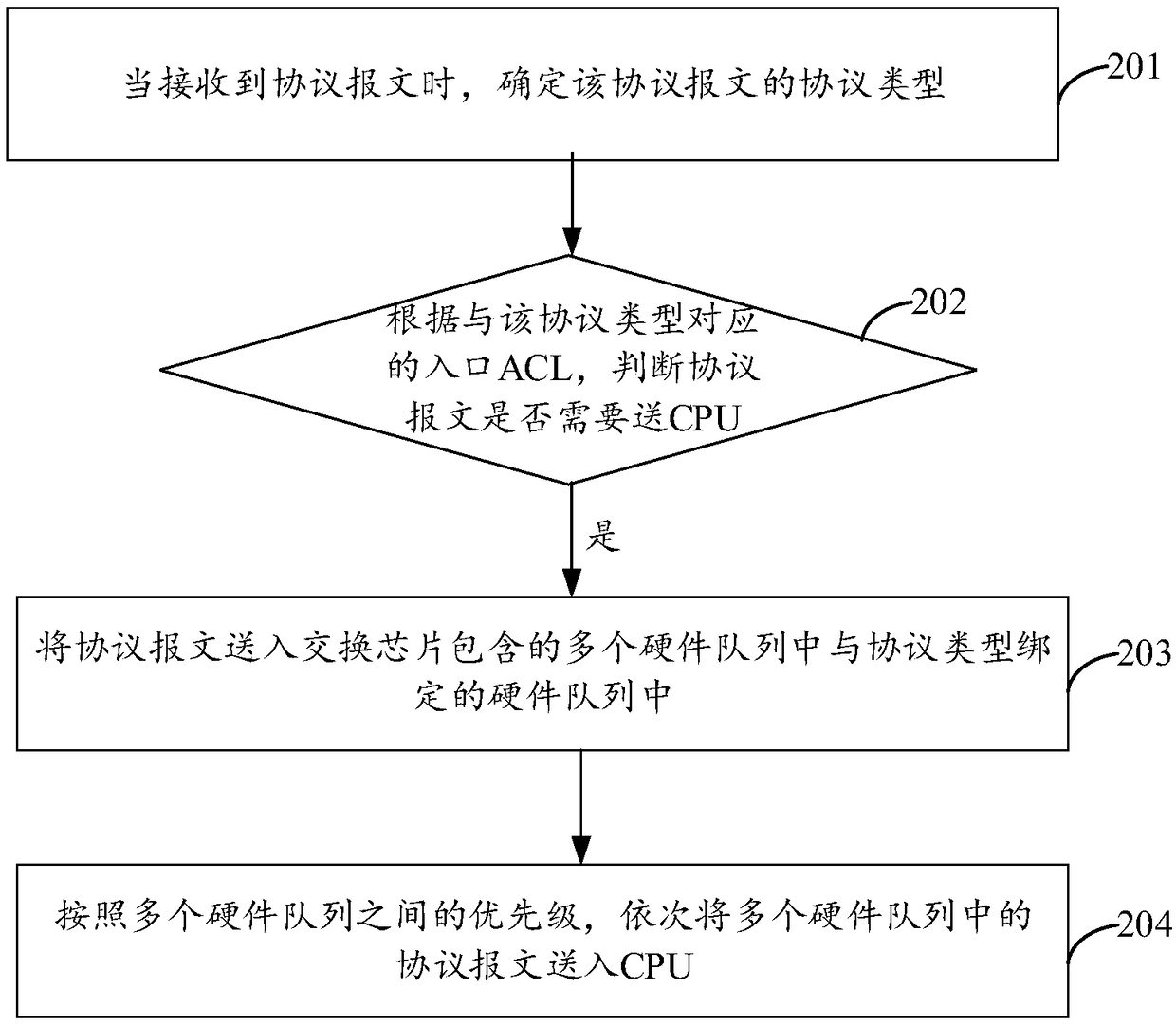
[0019] Aiming at the technical problem that the flow control method of the existing protocol message needs to consume CPU resources and increase the CPU load, the embodiment of the present application provides a solution, the basic idea is: on the one hand, by setting multiple protocol The ingress ACL of different types realizes a certain degree of pa...


PUM


Abstract

Embodiments of the present application provide a flow control method, a switch chip and a network device. On one hand, the embodiments of the present application realize flow control of massages on acertain degree at an entrance of the switch chip by setting entry ACLs with multiple protocol types at the entrance of the switch chip. On the other hand, the embodiments of the present application realize the flow control of protocol massages which are need to be send to CPU by configuring hardware queues with different priorities for protocol massages with different protocol types, and send theprotocol massages to the CPU in turn, according to the priority between multiple hardware queues. The embodiments of the present application realize the flow control of the protocol massages that needto be sent to the CPU on the switch chip by setting entry ACLs at the entrance of the switch chip and configuring the hardware queues with different priorities for the protocol massages with different protocol types. The whole process does not require the participation of the CPU, thereby helping to reduce the CPU resource consumption and reducing the running load of the CPU.

Description

technical field [0001] The present application relates to the technical field of wireless communication, and in particular to a flow control method, a switching chip and a network device. Background technique [0002] After a network device receives a message sent by another device, its switch chip can analyze the type of the message to determine whether the message is a protocol message or a data message. When it is determined that the message is a data message, there is no need to send it to a central processing unit (Central Processing Unit, CPU), and the switch chip can continue to perform other processing on the message. When it is determined that the packet is a protocol packet, such as an Address Resolution Protocol (Address Resolution Protocol, ARP) packet, the protocol packet will be sent to the CPU for related processing. However, the existing method of uploading protocol packets to the CPU may increase the CPU load and cause the CPU to crash. Contents of the in...

Claims


Application Information

Patent Timeline
Patent Type & Authority Applications(China)
IPC IPC(8): H04L12/865H04L12/933H04L12/851H04L29/06H04L47/6275
CPCH04L47/24H04L47/6275H04L49/10H04L63/101
Inventor 施世豪
Owner RUIJIE NETWORKS CO LTD
Learn More