
Air suspension and vehicle

An air suspension, air spring technology, applied in the direction of suspension, elastic suspension, vehicle components, etc., can solve the problem of insufficient space, air suspension is difficult to balance ride comfort and roll stiffness and cost layout space, air spring 2A Problems such as increase in size

Pending Publication Date: 2019-03-26
ZHEJIANG PANGOOD POWER TECH CO LTD
View PDF0 Cites 1 Cited by
  • Summary
  • Abstract
  • Description
  • Claims
  • Application Information

AI Technical Summary

Problems solved by technology

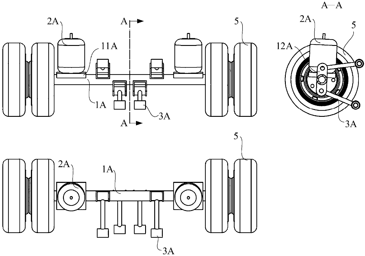
[0004] The feature of this solution is that, when the air spring 2A meets the load-bearing requirements, the roll stiffness of the vehicle body is reduced because the air spring 2A is located inside the wheel 5. In this case, to increase the roll stiffness, the air spring 2A must be increased. Rigidity can either increase the roll stabilizer bar or increase the center distance between the air springs 2A. Due to structural limitations, it is difficult to increase the center distance of the air spring 2A in the prior art, so the system is either installed with a roll stabilizer bar. Adding the stabilizer bar will cause Complicate the structure, or increase the stiffness of the air spring 2A. Increasing the stiffness of the air spring 2A will lead to an increase in the volume of the air spring 2A, which will cause a problem of insufficient space and increase the cost. The most important thing is to increase the air spring. 2A stiffness will result in reduced ride comfort
[0005] However, the above-mentioned air suspension is difficult to balance the contradiction between ride comfort, roll stiffness, cost, and layout space
Increasing the stiffness of the air spring 2A will increase the roll stiffness of the vehicle body, but will lead to a decrease in ride comfort. At the same time, the increase in the size of the air spring 2A will increase the occupied space and increase the cost

Method used


Image

  • Air suspension and vehicle
  • Air suspension and vehicle
  • Air suspension and vehicle

Examples


Embodiment

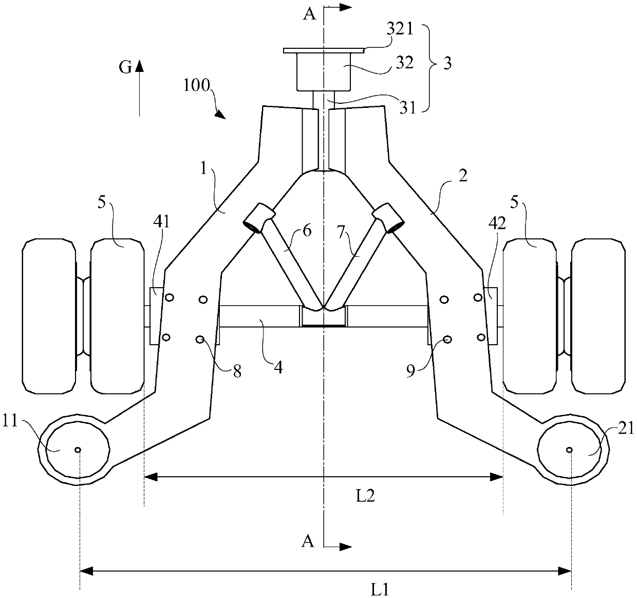
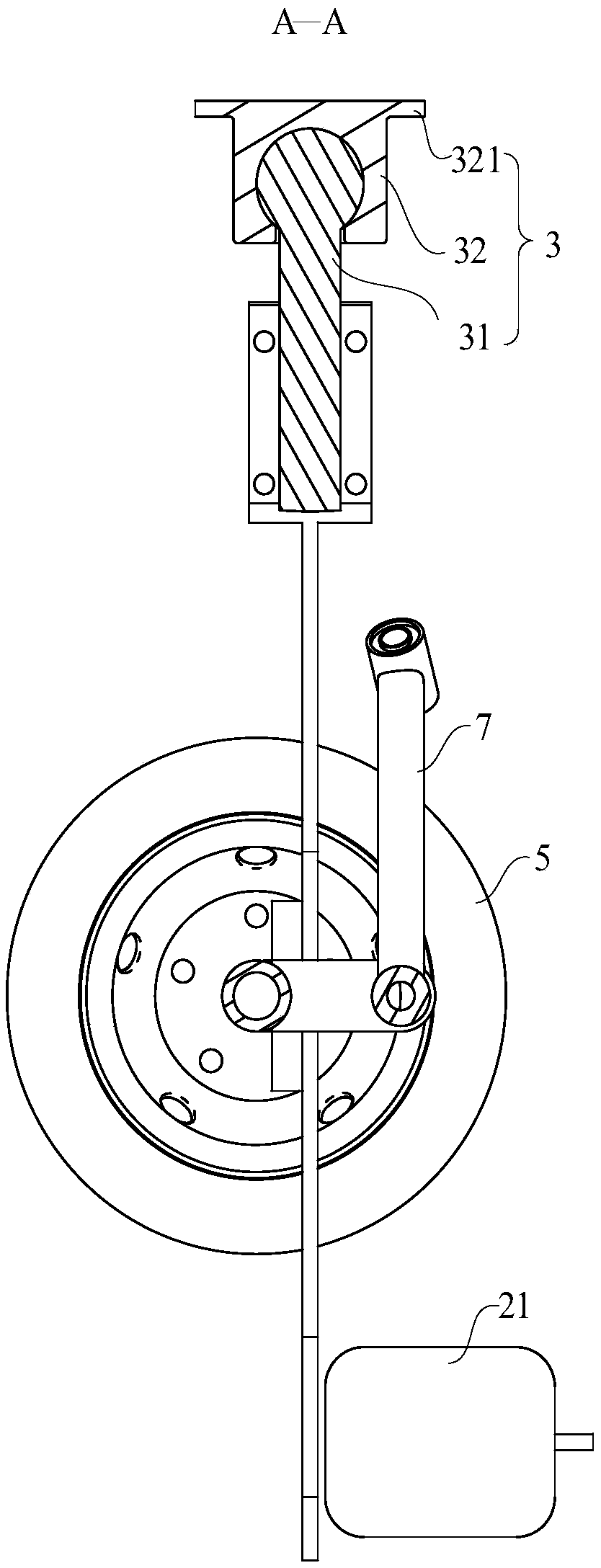
[0032] Please refer to Figure 2 to Figure 4, this embodiment provides an air suspension 100, which includes a first bracket 1 and a second bracket 2 whose middle sections are respectively fixedly connected to the axle 4. In this embodiment, the middle of the first bracket 1 Specifically, the segment can be fixedly connected to the first bracket arm support 41 welded on the vehicle axle 4 through the fixing bolt 8, and the middle section of the second bracket arm 2 can be fixedly connected to the bracket welded on the vehicle axle 4 through the fixing bolt 9. On the second support arm support 42. The first end of the first support arm 1 and the first end of the second support arm 2 are fixedly connected together, and the first end of the first support arm 1 and the first end of the second support arm 2 pass through a connecting assembly 3 together Connected to the vehicle body or frame, in this embodiment, the connection assembly 3 specifically includes a ball pin 31 that is ...


PUM


Abstract

The invention discloses an air suspension and a vehicle. The air suspension comprises an intermediate section, a first supporting arm and a second supporting arm fixed on and connected to an axle respectively; the first end of the first supporting arm is fixedly connected with the first end of the second supporting arm, the first ends of the first supporting arm and the second supporting arm are connected to a vehicle body or a vehicle frame through a connecting assembly jointly, the second ends of the first supporting arm and the second supporting arm extend to both ends of the axle respectively, and the distance between the second ends of the first supporting arm and the second supporting arm is greater than the distance between two tires connected to both ends of the axle; and the second ends of the first supporting arm and the second supporting arm are connected to the vehicle body or the vehicle frame through a first air spring and a second air spring respectively, and the first supporting arm and the second supporting arm form a V-shaped structure jointly.

Description

technical field [0001] The invention relates to the field of automobiles, in particular to an air suspension and a vehicle. Background technique [0002] With the rapid development of expressway in our country and the sudden increase of road transportation volume, as well as the improvement of people's requirements for ride comfort, handling stability and ride comfort of tractor vehicles, the application of air suspension in automobiles is becoming more and more extensive. [0003] figure 1 It is a structural schematic diagram of an air suspension in the prior art, please refer to figure 1 , the air suspension includes an air spring 2A, four pull rods 3A, a spring seat 11A and a tie rod bracket 12A, the spring seat 11A and the tie rod bracket 12A are welded on the axle 1A, and the lower end of the air spring 2A is fixed on the spring seat 11A with bolts, The other end is fixed on the vehicle frame or vehicle body by bolts, the tie rod 3A is hinged on the tie rod bracket 12...

Claims


Application Information

Patent Timeline
IPC IPC(8): B60G11/27B60G11/28
CPCB60G11/27B60G11/28
Inventor 史玉红毕兰平
Owner ZHEJIANG PANGOOD POWER TECH CO LTD
Learn More