
Image creating method and image creating system

a technology applied in the field of creating method and creating system, can solve problems such as problems such as the expansion of dither array, and achieve the effects of suppressing the variation in the distance between pixels, increasing the center-to-center distance, and reducing the reproducibility of an inherent original imag

Active Publication Date: 2012-01-10
RISO KAGAKU CORP
View PDF8 Cites 0 Cited by
  • Summary
  • Abstract
  • Description
  • Claims
  • Application Information

AI Technical Summary

Benefits of technology

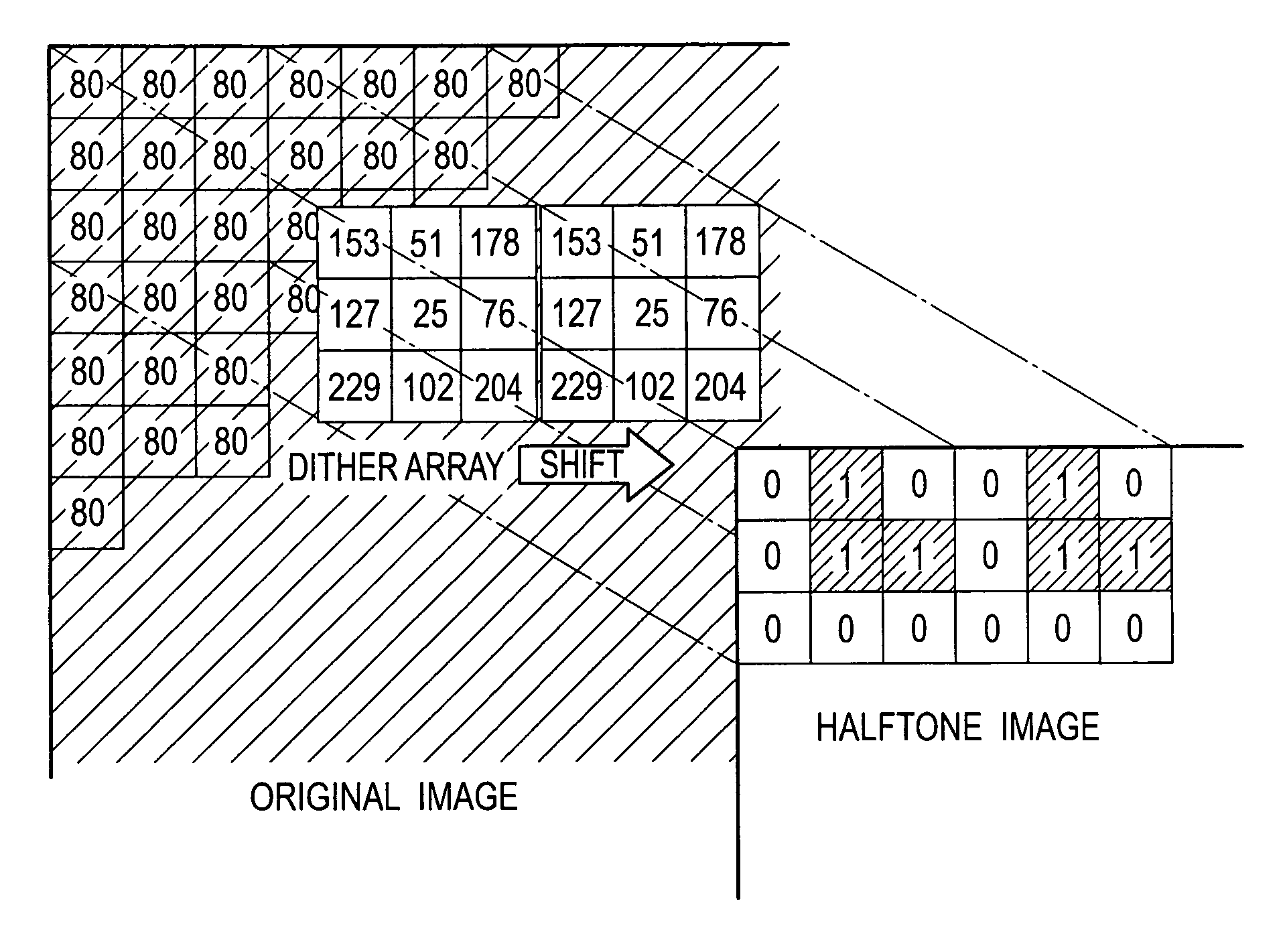
[0013]When compared with 3×3 dither arrays before and after a shift, 6×6 dither arrays before and after a shift have an increased center-to-center distance between those pixels to which their minimum thresholds are allotted. The center-to-center distance between such pixels of dither arrays is reflected on a center-to-center distance between corresponding black dots of neighboring halftone cells. As a result, in comparison with FIG. 10, FIG. 11 provides a halftone image with a reduced reproducibility of an inherent original image.
[0014]The present invention has been devised in view of such points. It therefore is an object of the present invention to provide an image creating method and an image creating system, allowing for a refined grayscale interval in halftone with a suppressed variation in distance between pixels of minimal thresholds in dither arrays.
[0016]According to the above aspect of the present invention, a halftone image creating method has lowest and near-lowest thresholds allotted to central pixels of sub-arrays of a dither array, thus allowing for a refined grayscale interval in halftone with a suppressed variation in distance between pixels of minimal thresholds in dither arrays.
[0018]According to the above aspect of the present invention, a halftone image creating system has lowest and near-lowest thresholds allotted to central pixels of sub-arrays of a dither array, thus allowing for a refined grayscale interval in halftone with a suppressed variation in distance between pixels of minimal thresholds in dither arrays.

Problems solved by technology

However, such a simple expansion of dither array involves an issue, as follows:

Method used


Image

  • Image creating method and image creating system
  • Image creating method and image creating system
  • Image creating method and image creating system

Examples


Embodiment Construction

[0055]There will de described the preferred embodiments of the present invention, with reference to the accompanying drawings.

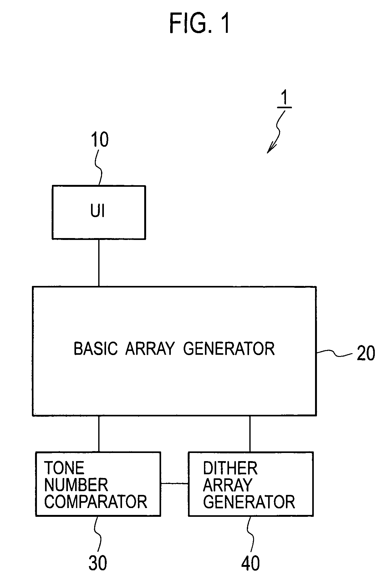
[0056]FIG. 1 is a schematic block diagram of an image creating system according to an embodiment of the present invention. The image creating system 1 includes a UI (user interface) 10, a basic array generator 20, and a dither array generator 40 provided with a tone number comparator 30.

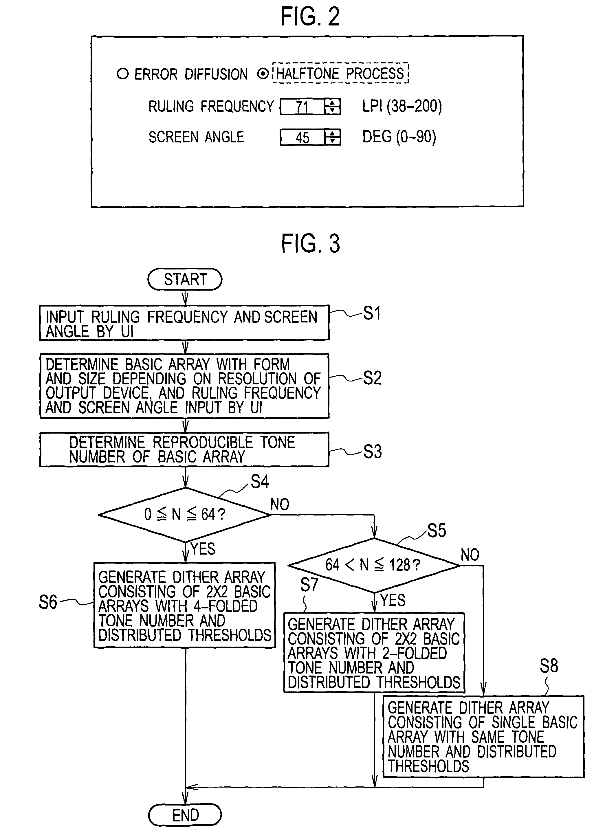
[0057]As shown in FIG. 2, the UI 10 is configured to input a screen ruling frequency (as a ruling frequency to be within a range of 38 to 200 lpi) and a screen angle (as an angle to be within a range of 0 to 90 degrees). The UI 10 is operable by the user to input an arbitrary ruling frequency and an arbitrary screen angle, so that the system 1 can acquire the ruling frequency and screen angle. Description will be made simply for screen angles of 0 and 45 degrees.

[0058]The basic array generator (as hardware or software) 20 is configured for automatic generation of an adequate a...


PUM


Abstract

For a halftone representation of a grayscale data of an original image of P tones, an output resolution, a screen ruling frequency, and a screen angle are based to set a basic array of L×L pixels, where L is an integer greater than 1, and a number N of tones reproducible by the basic array is compared with P to generate a dither array using the basic array as its sub-array, such that numbers are assigned to pixels of sub-arrays by a prescribed rule, in order between the sub-arrays, starting from prescribed ones of centered and centermost pixels of the sub-arrays.

Description

BACKGROUND OF TIE INVENTION[0001]1. Field of the Invention[0002]The present invention relates to an image creating method and an image creating system.[0003]2. Description of the Related Art[0004]In Japanese Patent Application Laying-Open Publication No. 2003-158633, there is disclosed a technique for image creation using a dithering method to halftone a set of grayscale or multi-tone data of an original image frame.[0005]The dithering method will be briefly described with reference to FIGS. 4 to 7.[0006]Now assumed is a set of original image data (i.e., a set of data on pixels in an original image frame) all being a data of 8 bits, i.e., 256 tones from “0 (white)” to “255 (black)”.[0007]Given in FIG. 4 are diagrams of exemplary dither arrays of a halftone cell in a digital halftone processing for an output under conditions: resolution 300 dpi, screen ruling frequency 100 lpi, and screen angle 0 deg. Generally, the “number of reproducible different tones” can be represented such tha...

Claims


Application Information

Patent Timeline
Patent Type & Authority Patents(United States)
IPC IPC(8): G06K9/36
CPCH04N1/4055H04N1/4058
Inventor KUROSE, TSUTOMU
Owner RISO KAGAKU CORP
Learn More