Logistics frame for logistics box transportation

A logistics box and logistics technology, which is applied in the field of logistics racks, can solve the problems of not being able to meet the needs of use, and can not adjust the transportation width, so as to achieve the effect of stable cargo transportation

Active Publication Date: 2019-03-26
JIANGSU ZHENG MAO MFG CO LTD
View PDF8 Cites 8 Cited by
  • Summary
  • Abstract
  • Description
  • Claims
  • Application Information

AI Technical Summary

Problems solved by technology

[0002] For example, the public number CN207045386U is a kind of shell delivery logistics rack without logistics box, including a base plate, a sliding plate, an outer fixing hole and an inner fixing hole, the bottom of the base plate is connected with a moving wheel, and the left side of the base plate is connected with a support frame, the upper end of the support frame is connected with a handle, the upper surface of the base plate is provided with a left chute and a right chute, the two sides of the base plate are provided with external fixing holes, and a sliding plate is placed on the base plate, The bottom of the sliding plate is connec

Method used


Image

  • Logistics frame for logistics box transportation
  • Logistics frame for logistics box transportation
  • Logistics frame for logistics box transportation

Examples


specific Embodiment approach 1

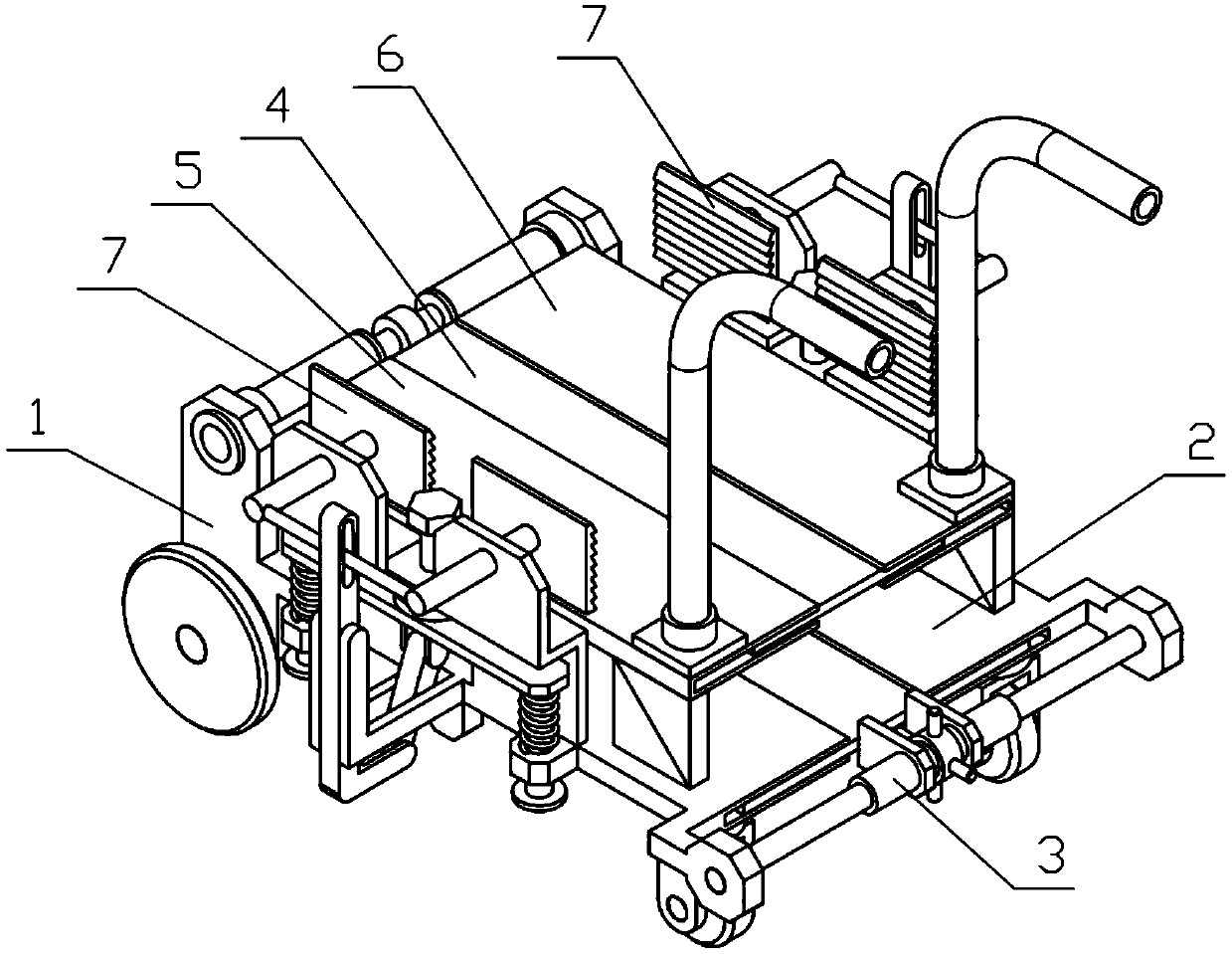
[0033] Combine below Figure 1-12 Describe this embodiment, a logistics box transport logistics rack, including side bracket I1, side bracket II2, sliding bracket 3, support bracket 4, transport bracket I5, transport bracket II6 and clamping mechanism 7, which can be installed on the sliding bracket 3 by rotating The sliding and turning handle 3-4 of the two sliding threaded rods 3-5 rotates in the opposite direction, pushing the side bracket I1 and the side bracket II2 on the sliding bracket 3 to perform the relative sliding between the side bracket I1 and the side bracket II2 The distance is changed, the side bracket I1 and the side bracket II2 respectively drive the transportation bracket I5 and the transportation bracket II6 to slide on the support bracket 4, and the relative distance between the transportation bracket I5 and the transportation bracket II6 is changed to change the width of the device, so that The device can be applied to goods of different widths and diffe...

specific Embodiment approach 2

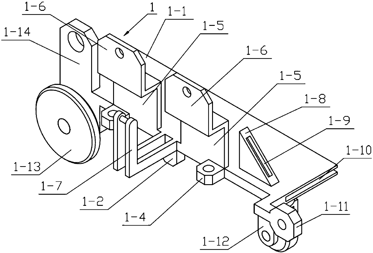
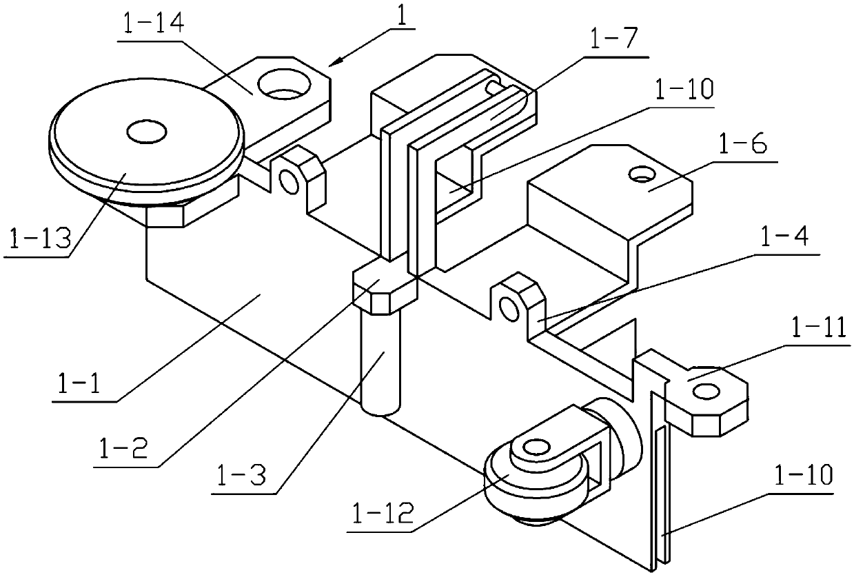
[0034] Combine below Figure 1-12 Describe this embodiment, this embodiment will further explain the first embodiment, the side bracket I1 includes the bottom plate I1-1, the lower connecting plate I1-2, the sliding cylinder I1-3, the sliding support plate I1-4, the support plate I1- 5. L-shaped support plate Ⅰ1-6, L-shaped connecting rod bracket Ⅰ1-7, triangular plate Ⅰ1-8, interference groove Ⅰ1-9, sliding groove Ⅰ1-10, rotating support plate Ⅰ1-11, universal wheel Ⅰ1- 12. The walking wheel I1-13 and the hinged support plate I1-14, the middle end of the lower side of the bottom plate I1-1 is fixedly connected with the lower connecting plate I1-2, and the lower connecting plate I1-2 is fixedly connected with the sliding cylinder I1-3, One side of the bottom plate I1-1 is fixedly connected with two sliding support plates I1-4, the other side of the bottom plate I1-1 is provided with a sliding groove I1-10, and one side of the upper end of the bottom plate I1-1 is fixedly conne...

specific Embodiment approach 3

[0035] Combine below Figure 1-12 Describe this embodiment, this embodiment will further explain the second embodiment, the side bracket II2 includes a bottom plate II2-1, a lower connecting plate II2-2, a sliding cylinder II2-3, a sliding support plate II2-4, and a support plate II2 -5, L-shaped support plate Ⅱ2-6, L-shaped connecting rod bracket Ⅱ2-7, triangular plate Ⅱ2-8, interference groove Ⅱ2-9, sliding groove Ⅱ2-10, rotating support plate Ⅱ2-11, universal wheel Ⅱ2 -12. Walking wheels Ⅱ2-13 and hinged support plate Ⅱ2-14, the middle end of the lower side of the bottom plate Ⅱ2-1 is fixedly connected with the lower connecting plate Ⅱ2-2, and the lower connecting plate Ⅱ2-2 is fixedly connected with the sliding cylinder Ⅱ2-3 , one side of the bottom plate Ⅱ2-1 is fixedly connected with two sliding support plates Ⅱ2-4, the other side of the bottom plate Ⅱ2-1 is provided with a sliding groove Ⅱ2-10, and one side of the upper end of the bottom plate Ⅱ2-1 is fixedly connected ...


PUM


Abstract

The invention relates to a logistics frame, specifically relates to a logistics frame for logistics box transportation, comprising a side bracket I, a side bracket II, a sliding bracket, a supportingbracket, a transportation bracket I, a transportation bracket II and a clamping mechanism; the relative distance between the side bracket I and the side bracket II sliding on the sliding support is changed by rotating a sliding rotating handle arranged on the sliding support and rotating threads on two sliding threaded rods in opposite directions; the side bracket I and the side bracket II respectively drive the transportation bracket I and the transportation bracket II to slide on the supporting bracket, and the relative distance between the transportation bracket I and the transportation bracket II is changed so that the width of the device is changed; and then the device can be suitable for goods with different widths and different transportation and using requirements; the goods can beclamped and unloaded by rotating the transportation bracket I and the transportation bracket II around the axis of a support sliding column arranged on the supporting bracket.

Description

technical field [0001] The invention relates to a logistics rack, in particular to a logistics box transportation logistics rack. Background technique [0002] For example, the public number CN207045386U is a kind of shell delivery logistics rack without logistics box, including a base plate, a sliding plate, an outer fixing hole and an inner fixing hole, the bottom of the base plate is connected with a moving wheel, and the left side of the base plate is connected with a support frame, the upper end of the support frame is connected with a handle, the upper surface of the base plate is provided with a left chute and a right chute, the two sides of the base plate are provided with external fixing holes, and a sliding plate is placed on the base plate, The bottom of the sliding plate is connected with a left slider and a right slider, the sides of the left slider and the right slider are provided with inner fixing holes, and the fixing bolts pass through the outer fixing hole...

Claims


Application Information

Patent Timeline
IPC IPC(8): B62B3/04B62B3/02
CPCB62B3/02B62B3/04
Inventor 张亮
Owner JIANGSU ZHENG MAO MFG CO LTD
Why Eureka
Try Eureka