Sea chest suction structure

A technology of seabed doors and suction inlets, which is applied to ships and other directions, and can solve problems such as insufficient cooling water for ships, affecting the safety and stability of ship navigation, and difficulty in entering water into the suction structure.

Pending Publication Date: 2019-03-26
广州船舶及海洋工程设计研究院(中国船舶集团有限公司第六〇五研究院)
View PDF0 Cites 1 Cited by
  • Summary
  • Abstract
  • Description
  • Claims
  • Application Information

AI Technical Summary

Problems solved by technology

The generation of vacuum water shortage area will lead to the difficulty of water intake in the suction structure, resulting in insufficient cooling water inside the ship, which will ultimately affect the safety and stability of ship navigation

Method used


Image

  • Sea chest suction structure
  • Sea chest suction structure
  • Sea chest suction structure

Examples


Embodiment Construction

[0016] Such as Figure 4-9 shown.

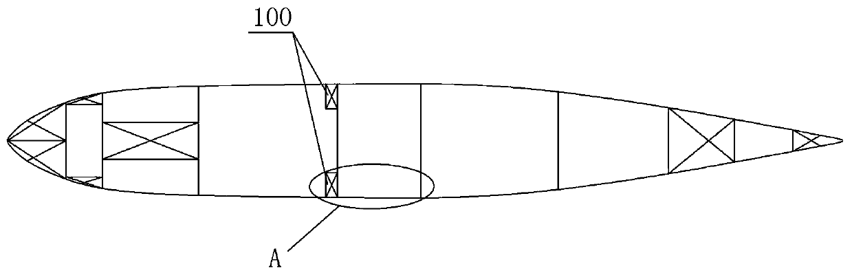
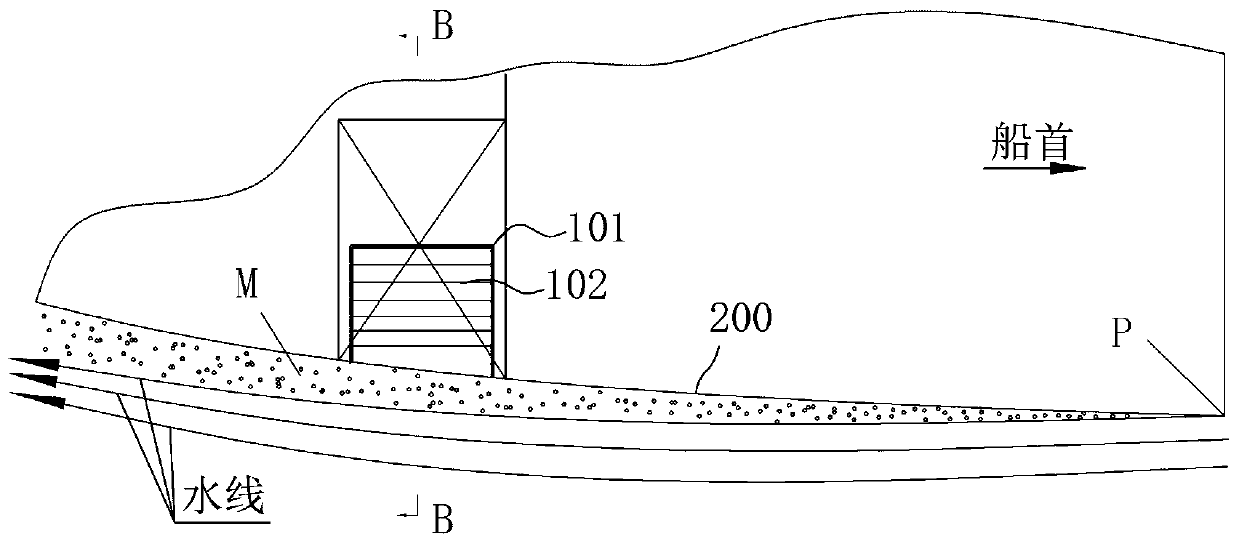
[0017] A seabed door suction structure, comprising a seabed door suction inlet 2 arranged on a ship's outer plate 200 and a water baffle 3 protruding outward from the hull, the water baffle is arranged on the ship's outer plate to communicate with the seabed door suction inlet Adjacent to or at the entrance of the suction inlet of the seabed door, and the water baffle is arranged in the range from the side of the suction inlet of the seabed door toward the stern to the side of the ship on both sides.

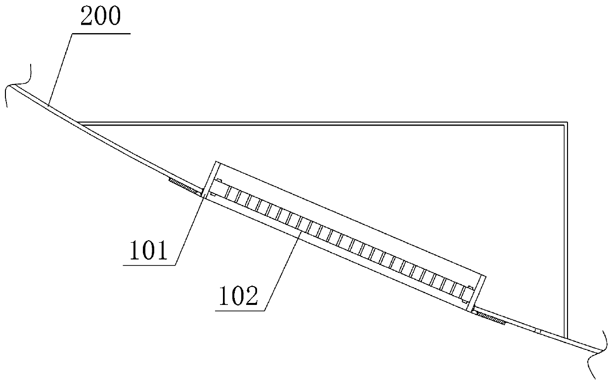
[0018] Such as Figure 4-6 As shown, a coaming plate 1 is installed on the suction port 2 of the seabed door, and the water retaining plate 3 is arranged on the outer surface of the coaming plate towards the stern side, and the rest of the coaming plate outer surface is consistent with the line shape of the ship's outer plate 200 . Alternatively, a filter device is provided on the enclosure 1, and the water retaining plate 3 is provided on t...


PUM


Abstract

The invention provides a sea chest suction structure. A water fender protruding outwards is arranged on a hull, and the water fender is arranged on the side, facing a stern, of a ship outer board or asuction opening of a sea chest or the adjacent position. When a ship navigates, currents flow through the front section of the suction opening of the sea chest firstly, part of the currents are sucked into the suction opening, the other part of the currents continue to flow to the water fender and are blocked by the water fender, part of the blocked currents slow down to stop at the position of the suction opening of the sea chest, the phenomenon of excessive vacuum water depletion is avoided, and therefore the currents stably and sufficiently flow into the ship to be cooled. By means of theheight, protruding out of the hull, of the water fender, generated ship resistance can be neglected while the suction performance is guaranteed. The sea chest suction structure is extremely simple, but the phenomenon of vacuum water depletion can be effectively solved, the water suction stability of the suction structure is guaranteed, and the operating stability and safety of the ship are also guaranteed.

Description

technical field [0001] The invention relates to the field of ship structures, in particular to a suction structure installed on a ship seabed door. Background technique [0002] Ships need a large amount of cooling water to cool their internal power plants and some auxiliary facilities during navigation. For this reason, seabed doors 100 are usually provided on both sides of the rear of the ship's bottom at the maximum width to inhale seawater for cooling, such as figure 1 shown. The outer plate of the hull is provided with a suction port of the seabed door, and the periphery of the suction port of the seabed door is provided with a coaming, and a filtering device such as a grille is installed in the middle of the coaming, through which the seawater can flow into the seabed tank, and the The sundries can be filtered. [0003] The existing submarine door suction structure such as figure 2 , 3 As shown, the seabed door suction inlet 102 is located on the hull panel 200, a...

Claims


Application Information

Patent Timeline
Patent Type & Authority Applications(China)
IPC IPC(8): B63B19/00
CPCB63B19/00
Inventor 杨涛王建彪姜华罗东宏杨蓬勃鲁寒坤伍东黄海彬尹杰
Owner 广州船舶及海洋工程设计研究院(中国船舶集团有限公司第六〇五研究院)
Why Eureka
Try Eureka