
Power electrical distribution cabinet for factory production and processing

It is a technology for electric power and factory production, which is applied in the substation/power distribution device shell, cooling/ventilation of substation/switchgear, etc. It can solve the problems of flying, affecting the factory working environment, and occupying factory space, so as to improve the working environment, The effect of preventing secondary flying and reducing occupancy

Inactive Publication Date: 2019-03-26
陈炜健
View PDF7 Cites 8 Cited by
  • Summary
  • Abstract
  • Description
  • Claims
  • Application Information

AI Technical Summary

Problems solved by technology

[0003] However, the existing power distribution cabinets have the following defects when they are placed in the factory: the distribution cabinet needs to reserve a channel with the wall to ensure that its heat dissipation function is not affected, and there are strict specifications for the distance from the wall, which leads to the installation of the power distribution cabinet. Due to the occupation of the factory space, and the cooling equipment in the power distribution cabinet is working, the air in the cabinet equipment is convected with the external air at the rear vent of the cabinet, so that the dust particles such as scraps and dust accumulated on the rear wall of the cabinet in the factory are re-flyed, affecting Working environment of factory production and processing

Method used


Image

  • Power electrical distribution cabinet for factory production and processing
  • Power electrical distribution cabinet for factory production and processing
  • Power electrical distribution cabinet for factory production and processing

Examples


Embodiment Construction

[0023] The following will clearly and completely describe the technical solutions in the embodiments of the present invention with reference to the accompanying drawings in the embodiments of the present invention. Obviously, the described embodiments are only some, not all, embodiments of the present invention.

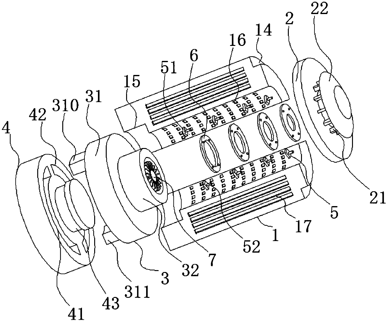
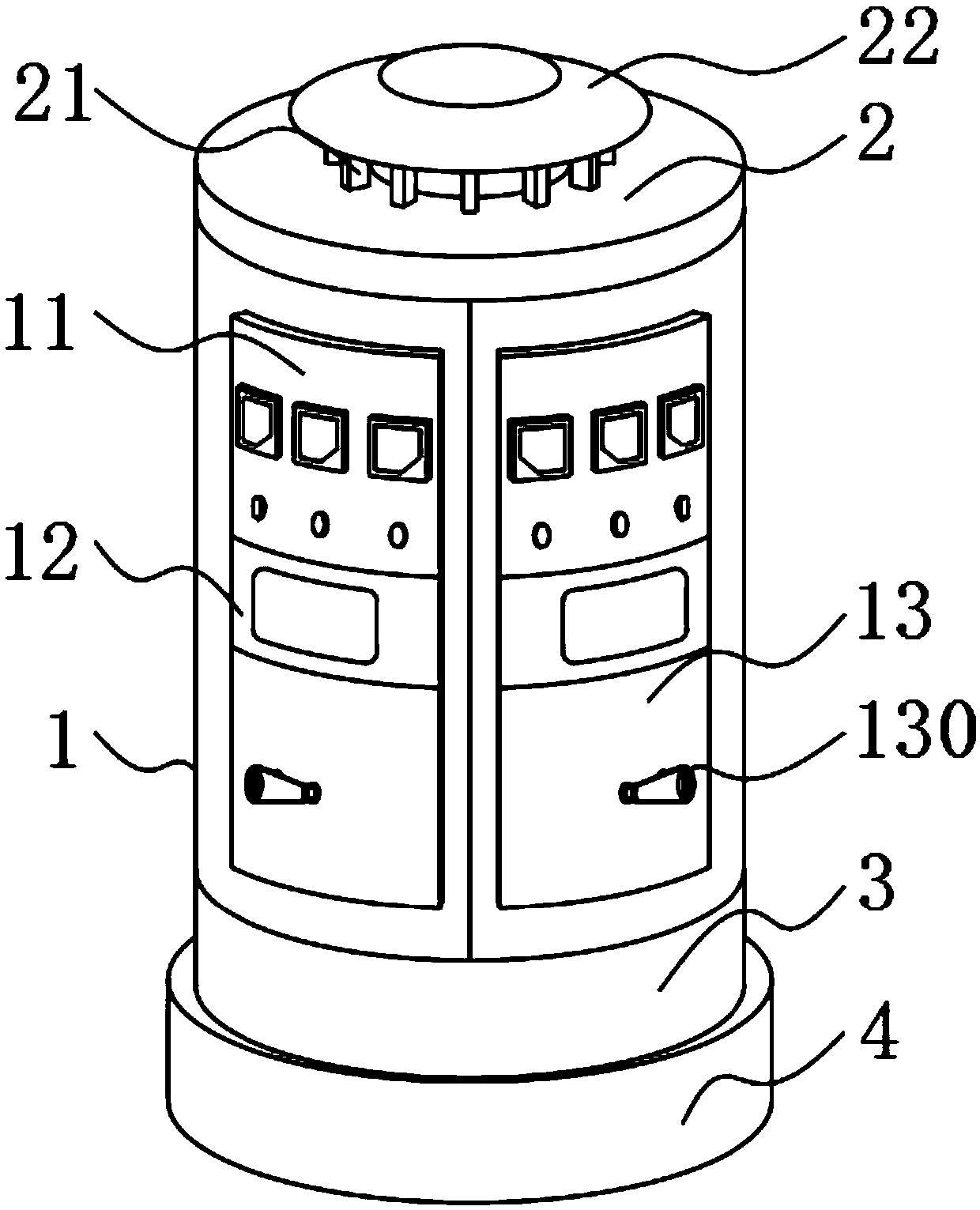
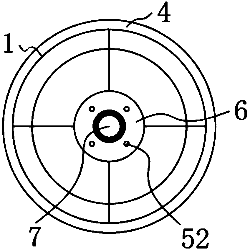
[0024] see Figure 1 to Figure 6 , the present invention provides a technical solution: an electric power distribution cabinet for factory production and processing, including a cabinet 1, a top cover 2 fixedly installed on the top of the cabinet 1, and an installation chassis 3 fixedly installed on the bottom of the cabinet 1, which is rotatably connected to Install the fixed chassis 4 at the bottom of the chassis 3, the fixed seat 5 fixedly connected to the inner side wall of the cabinet 1, and the partition ring 6 fixedly installed on the inner side wall of the cabinet 1, the number of cabinets 1 is four, and the four cabinets 1 form a hollow cylinder The outer si...


PUM


Abstract

The invention discloses a power electrical distribution cabinet for factory production and processing, which relates to the technical field of power equipment. The power electrical distribution cabinet includes cabinets, a top cover fixedly installed on the top of the cabinets, an installation chassis fixedly installed at the bottom of the cabinets, a fixed chassis rotationally connected to the bottom of the installation chassis, fixed seats fixedly connected to the inside walls of the cabinets, and spacer rings fixedly installed on the inside walls of the cabinets. There are four cabinets which form a hollow cylindrical shape. Through the setting of the cabinets forming a hollow cylindrical shape as well as heat dissipation holes in the inside walls of the cabinets, heat dissipation fan blades and a dust shield, heat dissipation can be carried out in the inner ring of the hollow cylinder formed by the cabinets. There is no need to reserve a channel between the distribution cabinet andthe wall for the placement of the distribution cabinet in a factory, and the operation of the heat dissipation equipment in the distribution cabinet is avoided. The air in the cabinet equipment exchanges with the outside air at the ventilation opening at the back of the cabinets. The factory space occupied by the distribution cabinet is reduced.

Description

technical field [0001] The invention relates to the technical field of electric equipment, in particular to an electric power distribution cabinet for factory production and processing. Background technique [0002] The power distribution cabinet is the final equipment of the power distribution system, which can provide protection, monitoring and control for the circuits of the factory's production and processing equipment. The staff and the material truck bumped into the power distribution cabinet. [0003] However, the existing power distribution cabinets have the following defects when they are placed in the factory: the distribution cabinet needs to reserve a channel with the wall to ensure that its heat dissipation function is not affected, and there are strict specifications for the distance from the wall, which leads to the installation of the power distribution cabinet. Due to the occupation of the factory space, and the cooling equipment in the power distribution c...

Claims


Application Information

Patent Timeline
Patent Type & Authority Applications(China)
IPC IPC(8): H02B1/56H02B1/30
Inventor 不公告发明人
Owner 陈炜健
Learn More