
Automatic rebar bending machine with adjustable bending angle and length

A bending angle and bending machine technology, applied in metal processing, metal processing equipment, manufacturing tools, etc., can solve the problems of inability to adjust the bending angle and length, time-consuming, laborious, and low efficiency, and achieve high precision and convenient use , the effect of improving work efficiency

Inactive Publication Date: 2019-03-29
缙云县乾恒商贸有限公司
View PDF1 Cites 10 Cited by
  • Summary
  • Abstract
  • Description
  • Claims
  • Application Information

AI Technical Summary

Problems solved by technology

[0005] The object of the present invention is to provide an automatic steel bar bending machine with adjustable bending angle and length, so as to solve the problem that manual bending is time-consuming and labor-intensive, and the efficiency is low. The existing bending machine cannot adjust the bending angle and length. question

Method used


Image

  • Automatic rebar bending machine with adjustable bending angle and length
  • Automatic rebar bending machine with adjustable bending angle and length
  • Automatic rebar bending machine with adjustable bending angle and length

Examples


Embodiment Construction

[0026] The following will clearly and completely describe the technical solutions in the embodiments of the present invention with reference to the accompanying drawings in the embodiments of the present invention. Obviously, the described embodiments are only some, not all, embodiments of the present invention. The specific embodiments described here are only used to explain the present invention, not to limit the present invention. Based on the embodiments of the present invention, all other embodiments obtained by persons of ordinary skill in the art without making creative efforts belong to the protection scope of the present invention.

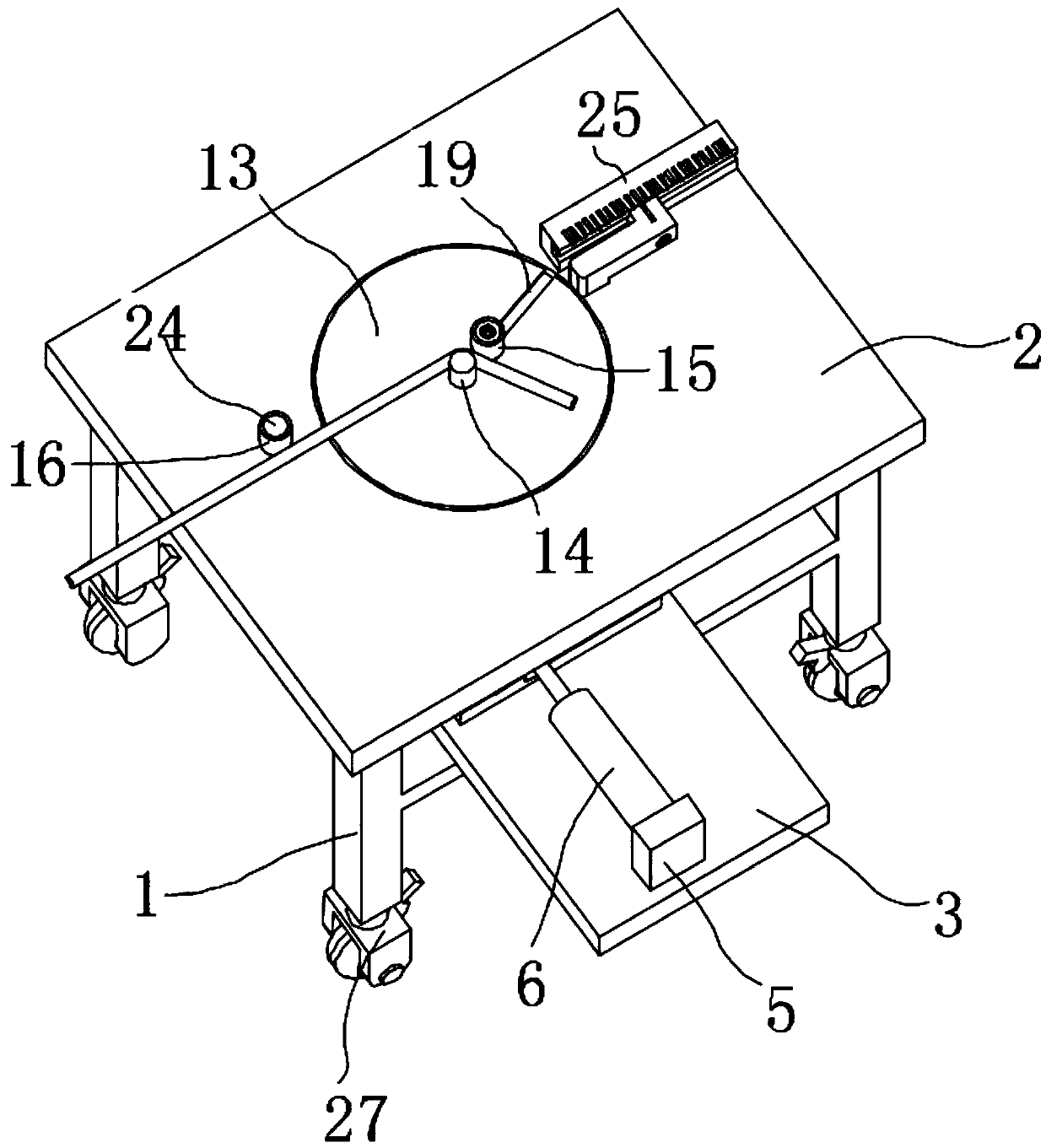
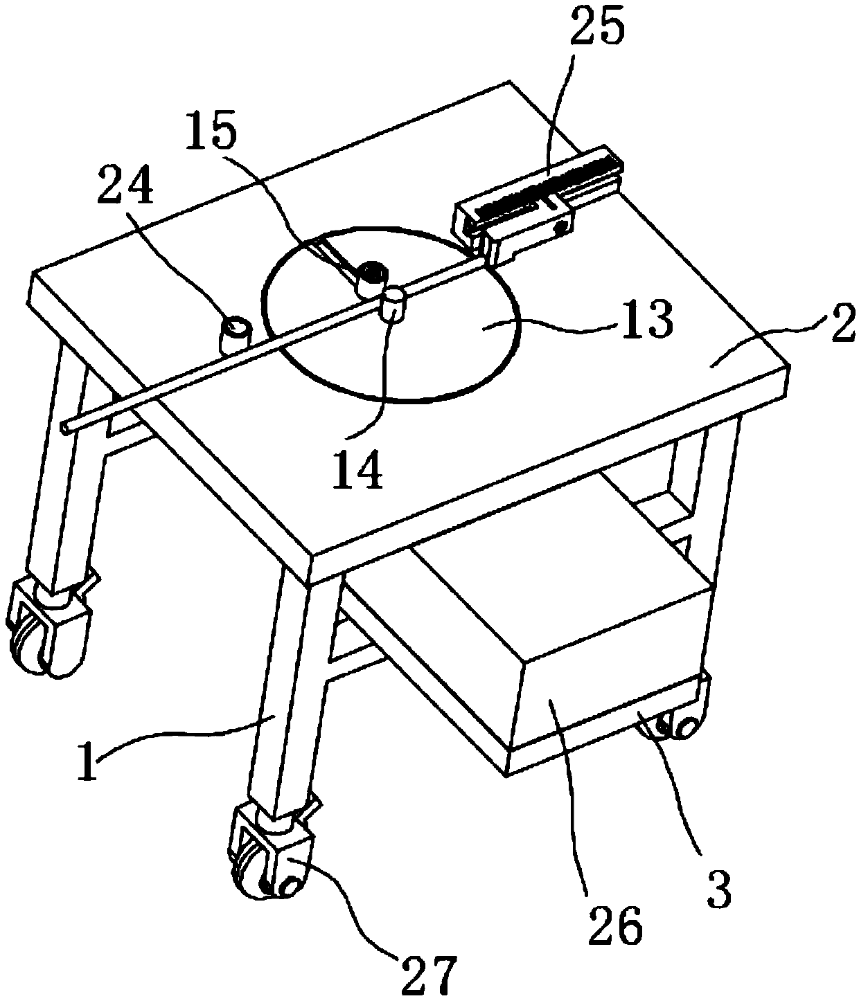
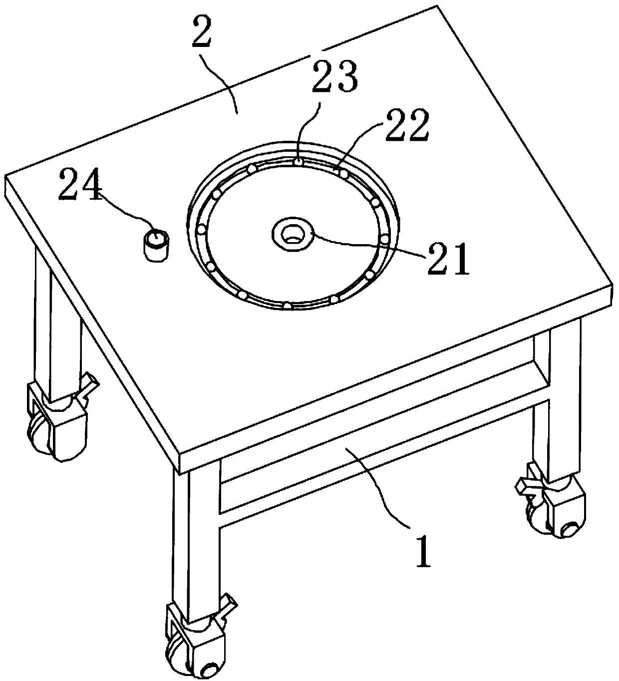
[0027] The present invention provides such Figure 1-7 The shown automatic steel bar bending machine with adjustable bending angle and length includes a frame 1, a workbench 2 is fixed on the upper end of the frame 1, and a fixing plate is fixed on the beam on the lower side of the frame 1 3. The first mounting block 5 is fixed on the up...


PUM


Abstract

The invention discloses an automatic rebar bending machine with adjustable bending angle and length. The automatic rebar bending machine comprises a frame, a working platform is fixedly arranged on anupper end of the frame, an electric telescopic rod is fixedly arranged on a first mounting block, and the first mounting block is arranged on the lower side of the frame; the end of the electric telescopic rod is fixedly provided with a straight rack, and the straight rack is slidably connected to a fixed block; a side of the straight rack is engaged with a gear, an inner circle of the gear is fixedly provided with a rotating shaft, the lower end of the rotating shaft is rotatably connected to the fixed block, and the upper end of the rotating shaft is fixedly provided with a turntable; the turntable is arranged in an inner cavity of the working platform, the center of the upper end of the rotating shaft is fixedly provided with a central shaft, and the upper end of the rotating shaft isfixedly provided with a bending shaft; and the upper end of a connecting shaft is rotatably connected to the working platform through a second bearing, a positioning shaft is fixedly arranged on one side of the upper end of the working platform, and one side of the upper end, away from the positioning shaft, of the working platform is fixedly provided with an adjusting mechanism. The automatic rebar bending machine can adjust and control the angle and the length of the bending of a rebar, the automatic rebar bending machine is convenient to use, the adjustment precision is high, and the work efficiency is improved.

Description

technical field [0001] The invention belongs to the technical field of bending equipment for building steel bars, and in particular relates to an automatic steel bar bending machine with adjustable bending angle and length. Background technique [0002] With the gradual development of my country's economic construction, large-scale construction projects are being carried out all over the country to build various residential buildings, office buildings, road works and other projects under construction. A large number of steel bars are bent. According to construction needs, the steel bars need to be bent into various angles. At present, workers usually use manpower to bend the two ends of the steel bar. Because the strength of the steel bar is generally high, manually bending the steel bar is a waste of the worker's physical strength. If the number of steel bars to be bent is large, the worker will spend a long time The physical strength of manual bending decreases rapidly, wh...

Claims


Application Information

Patent Timeline
Patent Type & Authority Applications(China)
IPC IPC(8): B21F1/00B21C51/00
CPCB21F1/00B21C51/00
Inventor 丁笔科
Owner 缙云县乾恒商贸有限公司
Learn More