Eureka AIR delivers breakthrough ideas for toughest innovation challenges, trusted by R&D personnel around the world.

A kind of shaping equipment for magnetic head automatic shell insertion

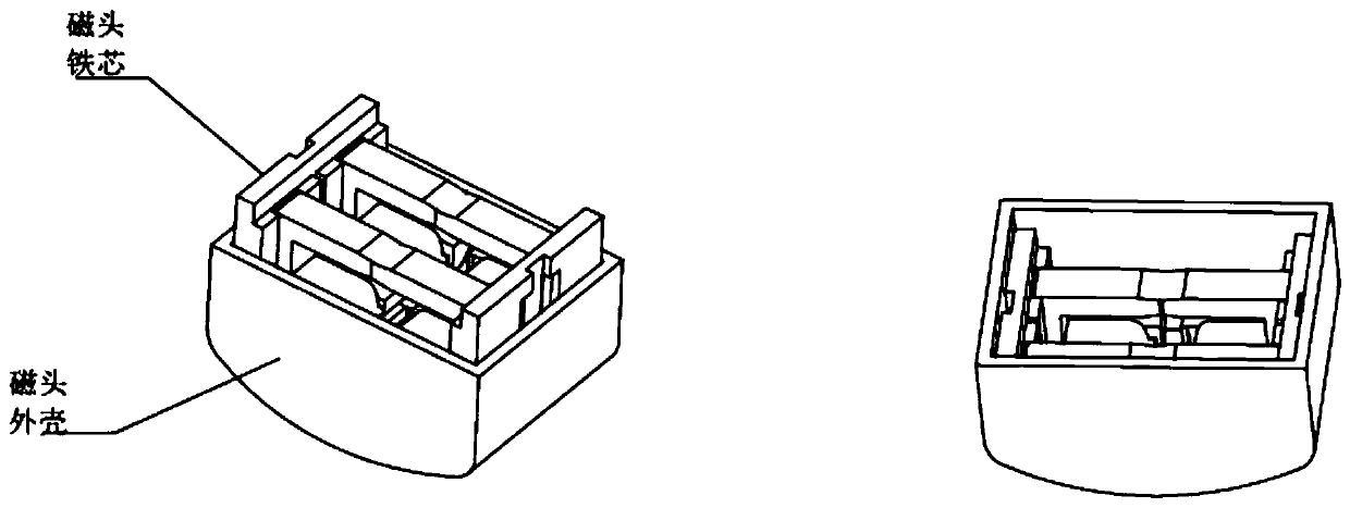
A magnetic head and equipment technology, applied in metal processing equipment, metal processing, manufacturing tools, etc., can solve problems such as low efficiency, fast wear of fixtures, and easy deviation of iron core groups

Active Publication Date: 2020-03-31
全南群英达电子有限公司
View PDF6 Cites 2 Cited by
  • Summary
  • Abstract
  • Description
  • Claims
  • Application Information

AI Technical Summary

Problems solved by technology

Take the magnetic head products that have been lined up in a row and neatly arranged on the magnetic head turnover plate from the previous (closed) process, and take the single product to a fixed position on the jig, and then press the cylinder switch to press into the iron. The core group is stamped to the specified position, and after the stamping and positioning are completed, they are placed back on the magnetic head turnover plate one by one. size), this method is inefficient, and the time for pressing the switch by hand is uncertain, because the product needs to be manually loaded and taken out, and the gap between the product grooves of the jig is too large, resulting in poor consistency of the product, and the iron core after entering the shell The group is easy to be biased, the jig wears quickly and the failure rate is high, and the jig is easy to punch and cause injury to the hand

Method used


Image

  • A kind of shaping equipment for magnetic head automatic shell insertion
  • A kind of shaping equipment for magnetic head automatic shell insertion
  • A kind of shaping equipment for magnetic head automatic shell insertion

Examples


Embodiment Construction

[0046]The technical solutions of the present invention will be further specifically described below through the embodiments and in conjunction with the accompanying drawings.

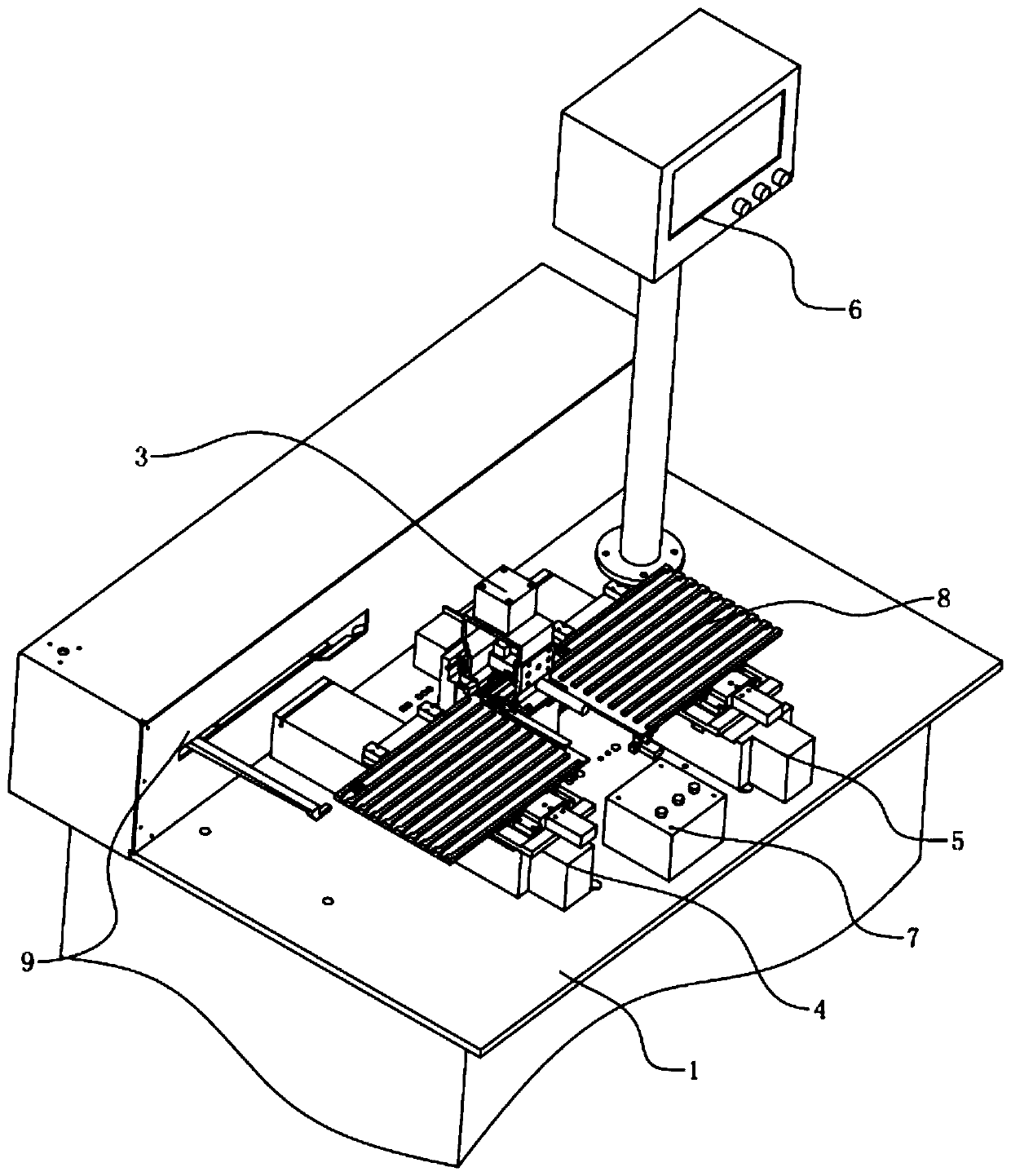
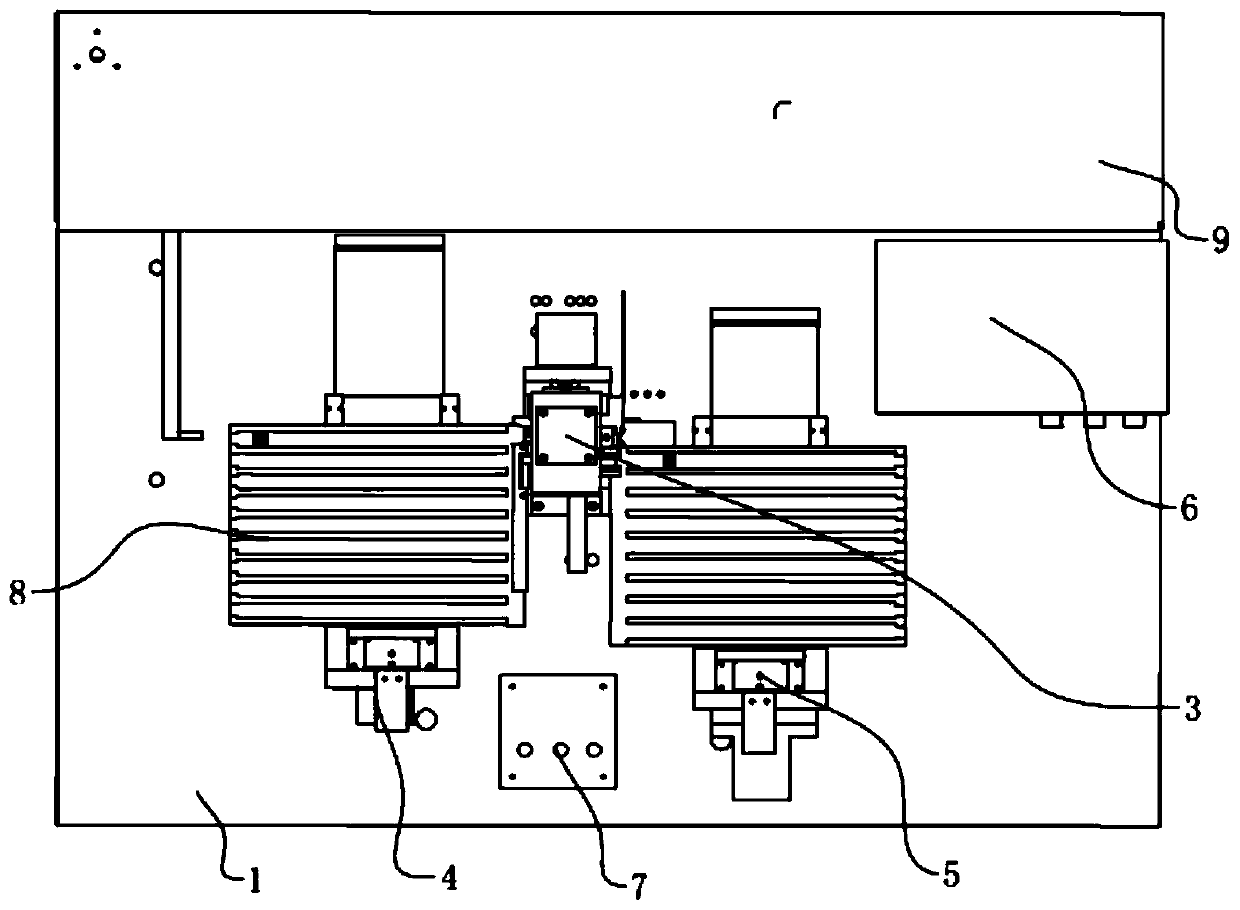
[0047] What needs to be explained in this embodiment is: since in this embodiment, both the feeding mobile slide 4 and the discharging mobile slide 5 contain components with the same structure and function, but in order to effectively distinguish them for a better understanding of the present invention Structure, in this embodiment, the writing in the feeding mobile slide table 4 is: slide table main body a41, servo motor a42, moving platform a43, positioning block a44, clamping cylinder a45, top plate a46; It is written as: sliding table main body b51, servo motor b52, moving platform b53, positioning block b54, clamping cylinder b55, and top plate b56.

[0048] In this embodiment, since the structure between the feeding moving slide 4 and the discharging moving sliding table 5 is the same, only the st...


PUM


Abstract

The invention relates to magnetic head automatic into-shell shaping equipment. The magnetic head automatic into-shell shaping equipment comprises a machine body; the top of the machine body is provided with a feeding moving slide table, an into-shell shaping mechanism, a discharging moving slide table and a touch screen controller, wherein the position, located on the rear sides of the feeding moving slide table, the into-shell shaping mechanism, the discharging moving slide table and the touch screen controller, of the top of the machine body is provided with a feeding pushing mechanism, andthe position, located on the front side of the into-shell shaping mechanism, of the top of the machine body is provided with a control switch; the touch screen controller is connected with the feedingmoving slide table, the into-shell shaping mechanism, the discharging moving slide table and the feeding pushing mechanism; the control switch is connected with the feeding moving slide table and thedischarging moving slide table; and the feeding moving slide table and the discharging moving slide table are both provided with magnetic head turnover plates. According to the magnetic head automatic into-shell shaping equipment, a magnetic head is subjected to automatic feeding positioning and punching and shaped to the specified dimension, and the punching and shaping steps of the magnetic arecompleted on the same jig.

Description

technical field [0001] The invention relates to the technical field of electronic components, in particular to a shaping device for automatic casing insertion of a magnetic head. Background technique [0002] The original method of inserting the magnetic head into the shell is to press the iron core of the magnetic head into the specified position inside the shell of the magnetic head, and to ensure that the shell does not expand and deform due to the iron core being installed. A orthopedic fixture. It needs to be completed in 2 parts. Take the magnetic head products that have been lined up in a row and neatly arranged on the magnetic head turnover plate from the previous (closed) process, and take the single product to a fixed position on the jig, and then press the cylinder switch to press into the iron. The core group is stamped to the specified position, and after the stamping and positioning are completed, they are placed back on the magnetic head turnover plate one b...

Claims


Application Information

Patent Timeline
Patent Type & Authority Patents(China)
IPC IPC(8): B23P19/027B21D3/00
CPCB21D3/00B23P19/027
Inventor 古东昌梁志吉
Owner 全南群英达电子有限公司
Why Eureka
Eureka Blog
Learn More