
Disc cutter changing robot simulation test bed and application method thereof

A technology for simulating test benches and disc-shaped hobs, applied in manipulators, manufacturing tools, etc., can solve problems such as high cost, difficult tool box position changes, complex structures, etc., and achieve the effect of easy handling and saving test costs

Active Publication Date: 2019-03-29
NORTHEASTERN UNIV
View PDF6 Cites 3 Cited by
  • Summary
  • Abstract
  • Description
  • Claims
  • Application Information

AI Technical Summary

Problems solved by technology

[0005] (1) The structure is complex and the functions are limited: Since the designed shield machine simulation test bench is mainly used for dynamic simulation, it tries to restore the real situation as much as possible. The structural design is equivalent to the size of the real shield machine, which is not suitable for laboratory environment processing. and building physical models;
[0006] (2) The position of the knife box is fixed: the more common shield machine simulation test bench generally adopts a fixed structure, and it is difficult to change the position of the knife box after the construction is completed;
[0007] (3) The cost of laboratory construction is high: the shield machine simulation test bench used in simulation analysis is a large-scale structural design, and it will cost a lot to build a solid model in the laboratory environment

Method used


Image

  • Disc cutter changing robot simulation test bed and application method thereof
  • Disc cutter changing robot simulation test bed and application method thereof
  • Disc cutter changing robot simulation test bed and application method thereof

Examples


Embodiment Construction

[0044] The present invention will be further elaborated below in conjunction with the accompanying drawings of the description.

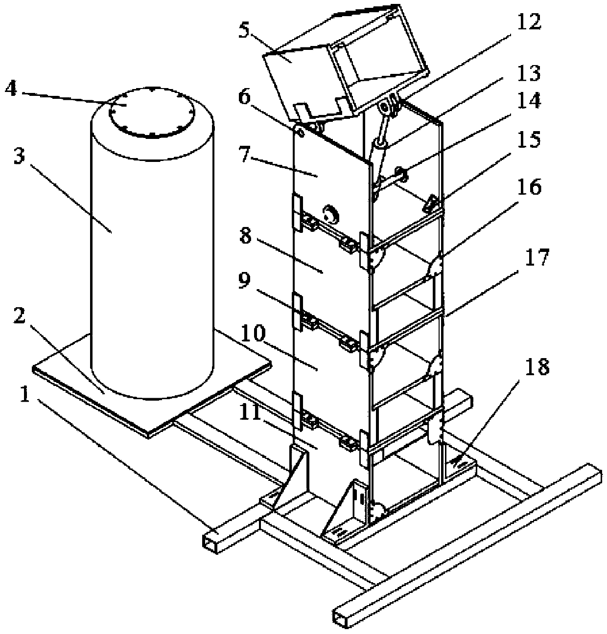
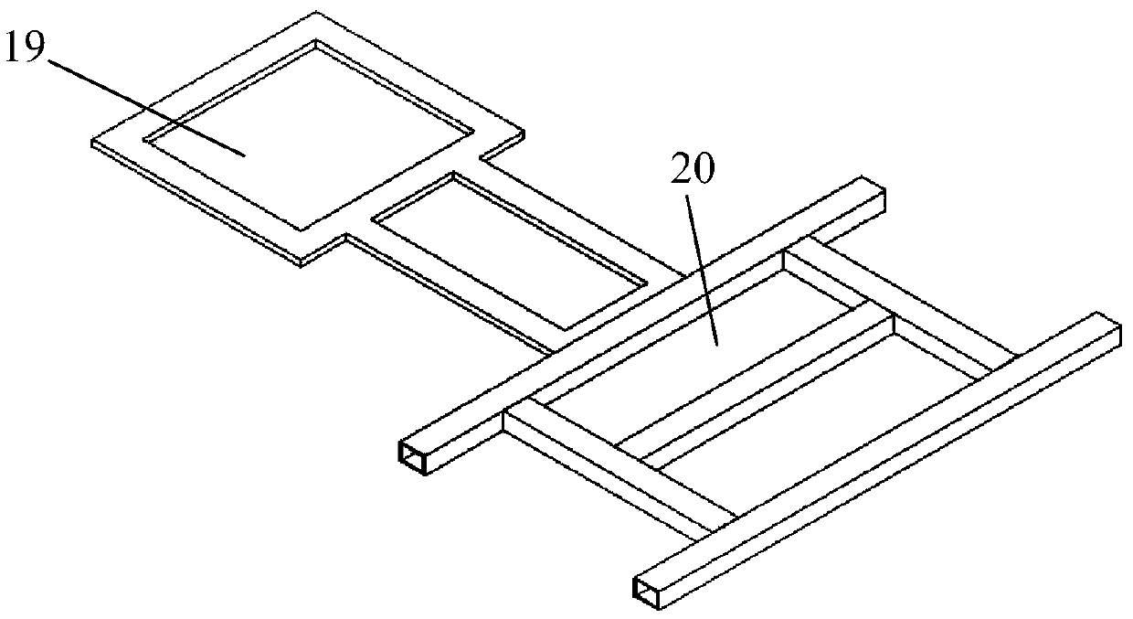
[0045] Such as figure 1 , 2 As shown, a simulation test bench for a disc-shaped hob tool changing robot of the present invention includes a test bench base 1, a tool changing robot mounting seat and a tool box module, wherein the test bench base 1 includes a tool changing robot mounting seat area 19 and The knife box module area 20 is installed, and the tool changing robot mounting seat is installed on the tool changing robot mounting seat area 19; the knife box module is installed on the knife box module area 20.

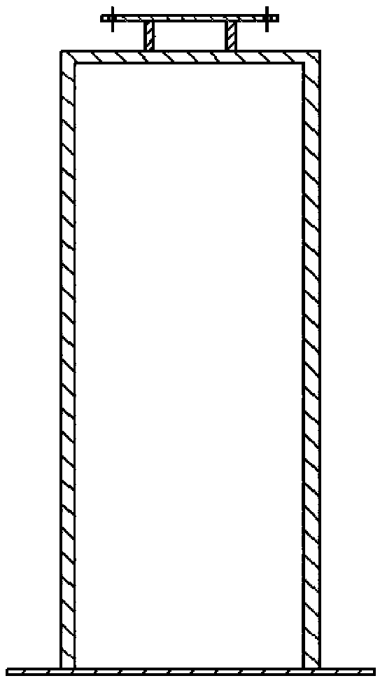
[0046] The tool changing robot mounting base comprises a tool changing robot mounting base base plate 2, a tool changing robot mounting base base 3 (such as image 3 shown) and the flange disc 4 of the tool changing robot mounting base, wherein the tool changing robot mounting base base 3 is installed on the tool changing robot mountin...


PUM


Abstract

The invention relates to a disc cutter changing robot simulation test bed and an application method thereof. The test bed comprises a test bed base, a cutter changing robot mounting seat and a cutterbox module, wherein the test bed base comprises a cutter changing robot mounting seat area and a cutter box module mounting area, the cutter changing robot mounting seat is installed on the cutter changing robot mounting seat area, and the cutter box module is installed on the cutter box module mounting area. The method comprises the following steps that the test bed is built according to test requirements; a cutter box inclination set angle of an inclination angle-variable cutter box module is simulated; and through change of tightening positions of long-strip-shaped threaded through holes ina triangular support assembly, overall transverse movement of a cutter box module combination is realized. According to the disc cutter changing robot simulation test bed and the application method thereof, all the modules are freely combined and assembled so that the actual working conditions can be reflected more truly, convenience can be provided for optimizing the structure and mechanism precision and reliability test of the intelligent cutter changing robot, the test cost is saved, the experiment effect is good, and the construction of a physical prototype test bed becomes simple and easy.

Description

technical field [0001] The invention relates to a simulation test bench for a disc-shaped hob tool-changing robot and a use method thereof, in particular to a disc-shaped hob knife-change robot simulation test bench and a use method thereof. Background technique [0002] The research in the field of shield machine test-bed design mainly focuses on two aspects: simulation test-bed design and laboratory environment test-bed design. The simulation test bench is for mechanical analysis experiments; the laboratory environment test bench is generally used in conjunction with the tool changing robot, which has important practical significance. my country's railway and highway traffic tunnels, and the construction of gas and oil pipeline tunnels also have huge room for development. During the tunnel excavation process of shield machines, the design of tool replacement robots or other auxiliary mechanisms has become a hot issue. It is very urgent to design a simulation test bench fo...

Claims


Application Information

Patent Timeline
IPC IPC(8): B25J19/00
CPCB25J19/00B25J19/0095
Inventor 李海洋谢里阳刘生磊穆童
Owner NORTHEASTERN UNIV
Learn More