Supercharge Your Innovation With Domain-Expert AI Agents!

A Differentially Variable Pitch Blade and Helicopter Rotor System

A variable-pitch blade and rotor shaft technology, applied in rotorcraft, motor vehicles, aircraft, etc., can solve the problems of affecting the lift of the tip part, the overall weight of the rotor device, and the sticking of the blades, so as to reduce the power transmission link. , Improve the efficiency of energy transfer and avoid friction loss

Active Publication Date: 2020-08-14
CHINA HELICOPTER RES & DEV INST
View PDF5 Cites 0 Cited by
  • Summary
  • Abstract
  • Description
  • Claims
  • Application Information

AI Technical Summary

Problems solved by technology

[0004] The power of the conventional rotor device is mechanically converted and transmitted through the engine and the transmission, and there is a power loss and the system is complicated; there is air convection above and below the blade section at the blade tip of the rotor blade, which reduces the airflow above and below the blade section. The pressure difference affects the ability of the blade tip to generate lift; at the same time, the inconsistent airflow environment of each section of the blade brings uneven force on each section of the blade, resulting in the problem of low fatigue life of the blade; and the blade is bare. , will collide with external objects, affecting flight safety. At the same time, the noise generated by the rotor blades is not shielded, and it is directly transmitted to the outside world. The overall noise is large
[0005] Because the blade rotates at a position with a larger radius, the faster the linear speed is, and the lift generated at this position is also greater. Generally, the resultant lift force of the blade is at a position about 70% of the blade radius away from the rotation axis of the blade, that is, a position far away from the rotor axis. , while the bearing position of the conventional rotor device is at the center, that is, the rotor shaft, so the moment arm between the lift force of the blade and the bearing position of the rotor shaft is relatively long, resulting in a large bending moment for the blade, propeller hub and rotor shaft, resulting in vibration Large, low fatigue life issues
[0006] In order to solve the problem of complex rotor mechanism and large load, and reduce friction loss at the same time, there is a patent for supporting the rotor by magnetic levitation, but there are also problems such as uncompact structure, complex mechanism, blade angle of attack adjustment (blade angle of attack adjustment can be changed) The magnitude and direction of the lift force of the rotor, and then adjust the overall flight speed, attitude, etc. of the aircraft) and other problems.
[0007] In the patent of the World Intellectual Property Office with the publication number WO2015005776A1 and the US patent with the publication number US7802755B2, the entire guide rail ring covered with the load-carrying unit is used, while the patent with the publication number WO2005072233A2 uses a ready-made magnetic suspension bearing, and the effect is the same as before. The two patents are similar. This integral guide rail ring is not conducive to the installation of other devices such as control equipment, and requires additional additional mechanisms. The structure is not compact, which will increase the weight of the system and affect the transportation efficiency of the aircraft. For example, the distance change mechanism of the patent WO2005072233A2 Blade angle of attack to adjust the rotor lift) additional installation mechanism is required, resulting in larger system size, complex mechanism and heavy weight
[0008] The Chinese patent with the publication number CN101693470B provides a magnetic levitation electric rotor flying saucer, and the Chinese patent with the publication number CN102085912A provides a dish-shaped magnetic levitation ring-wing aircraft. There are two sets of magnetic levitation guide rails in the outer ring, the system is relatively complicated, and the overall weight of the rotor device is too large; at the same time, there are also situations in which the aerodynamic loads on the root and end of the rotor blades are inconsistent due to the difference in the airflow environment in a complex airflow environment. The resulting discrepancies in the rotational angular velocity of the blades at the root and at the end may lead to the possibility of misalignment of the blades on the inner and outer ring guide rails, which will seriously cause the blades to become stuck
[0009] The blade pitch change mechanism described in patent WO2005072233A2 can only adjust the angle of attack of the blade as a whole, and can only change the magnitude of the lift force, and cannot simultaneously meet the requirements of maintaining high efficiency of the rotor under various incoming flow speeds

Method used


Image

  • A Differentially Variable Pitch Blade and Helicopter Rotor System
  • A Differentially Variable Pitch Blade and Helicopter Rotor System
  • A Differentially Variable Pitch Blade and Helicopter Rotor System

Examples


no. 1 example

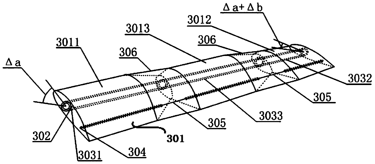
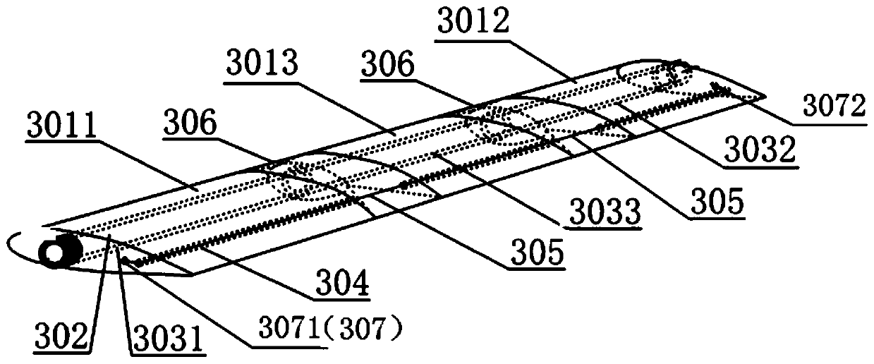
[0034] The first aspect of the present application provides a differentially variable pitch blade, such as figure 1 As shown, a first embodiment is provided, which includes:

[0035] At least two airfoil sections 301 are rotationally connected between adjacent airfoil sections, and each airfoil section has a first through hole and a second through hole;

[0036] The torsion rod 302 is penetrated and rotatably arranged in the first through holes of all the airfoil sections; and

[0037]The variable-pitch control cable 305 runs through the second through holes of all the airfoil sections, and the two ends of the variable-pitch control cable 305 are respectively fixed on the airfoil sections at the blade root and the blade tip;

[0038] Wherein, the first airfoil section at the root of the blade is connected with a first torsion mechanism for driving the first airfoil section to twist a first angle, and the second airfoil section at the tip of the blade is connected with a secon...


PUM


Abstract

A differential variable pitch blade, comprising: at least two airfoil sections (301), the adjacent airfoil sections (301) being rotatably connected, each airfoil section (301) being provided with a first through hole and a second through hole; a torsion bar (302), penetratingly and rotatably arranged within the first through holes of all the airfoil sections (301); a variable pitch control cable (305), penetratingly arranged within the second through holes of all the airfoil sections (301), two ends of the variable pitch control cable (305) being respectively fixed on the airfoil sections at the blade root and the blade tip, wherein a first airfoil section located at the blade root is connected to a first twist mechanism used for driving the first airfoil section to twist by a first angle, and a second airfoil section located at the blade tip is connected to a second twist mechanism used for driving the second airfoil section to twist by a second angle. The variable pitch control cable (305) and the torsion bar (302) transfer torsion forces located at a blade root portion and a blade tip portion to a blade central portion, so that the airfoil sections located at the blade central portion twist in a synchronous manner, thereby reducing power transfer links, and improving energy transfer efficiency.

Description

technical field [0001] The invention belongs to the technical field of rotor blade design, in particular to a differentially variable pitch blade and a helicopter rotor system. Background technique [0002] The rotor of the rotorcraft generates aerodynamic force through rotation, which provides lift for the flight, so that it has the ability to take off and land vertically. The selection of the take-off and landing site is more flexible and the operation range is wide. While providing lift, the rotor can also produce the steering force required for flight in all directions. [0003] A conventional rotor device is composed of rotor blades, a rotor hub, and a rotor shaft. The rotor blades are installed on the rotor hub. The rotor hub is connected to the transmission system through the central rotor shaft. The driving force of the power system is decelerated through the transmission device through multi-stage gear transmission. Finally, it is transmitted to the rotor shaft, wh...

Claims


Application Information

Patent Timeline
Patent Type & Authority Patents(China)
IPC IPC(8): B64C27/473B64C27/46B64C27/32B64C27/80
CPCB64C27/32B64C27/46B64C27/473B64C27/80
Inventor 刘衍涛
Owner CHINA HELICOPTER RES & DEV INST
Features
  • R&D
  • Intellectual Property
  • Life Sciences
  • Materials
  • Tech Scout
  • Unparalleled Data Quality
  • Higher Quality Content
  • 60% Fewer Hallucinations
Learn More