Anaerobic tank for sewage treatment

A sewage treatment and anaerobic pool technology, applied in biological water/sewage treatment, water/sludge/sewage treatment, anaerobic digestion treatment, etc., can solve the problems of incomplete purification and poor sealing, and achieve the solution of incomplete purification , Improve the sealing performance and improve the purification effect

Inactive Publication Date: 2019-03-29
南京壹久软件科技有限公司
View PDF0 Cites 1 Cited by
  • Summary
  • Abstract
  • Description
  • Claims
  • Application Information

AI Technical Summary

Problems solved by technology

[0004] The purpose of the present invention is to provide an anaerobic tank for sewage treatment to solve the problems of poor sealing and incomplete purification of the anaerobic tank for sewage treatment proposed in the above background technology

Method used


Image

  • Anaerobic tank for sewage treatment
  • Anaerobic tank for sewage treatment
  • Anaerobic tank for sewage treatment

Examples


Embodiment 1

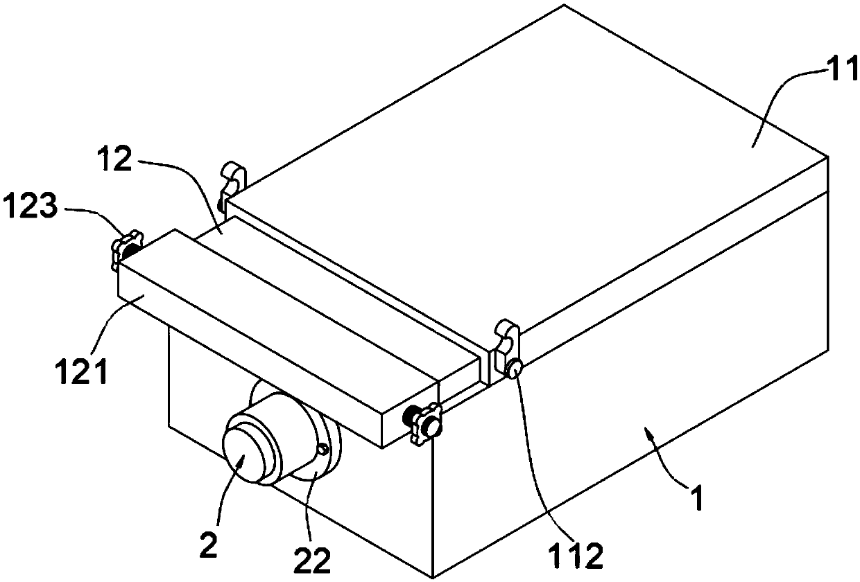
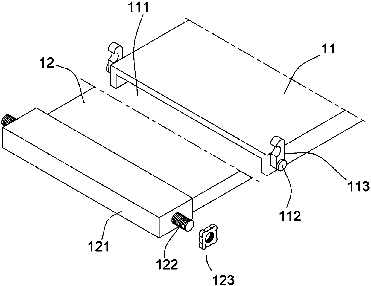
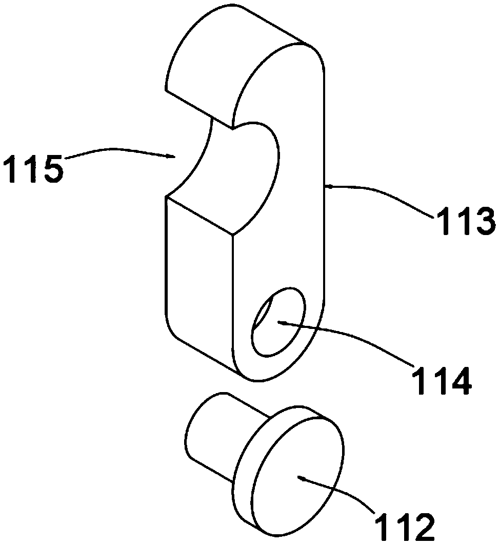
[0031] An anaerobic pond for sewage treatment, such as figure 1 , figure 2 and image 3 As shown, including the anaerobic pool 1, the upper surface of the anaerobic pool 1 is tightly welded with a loam cake 11, the lower surface of the loam cake 11 is provided with a slideway 111, and the slideway 111 is provided with a slide plate 12, and the slide plate 12 passes through the slideway 111 is slidingly connected with the upper cover 11, one end of the slide plate 12 is tightly welded with a stopper 121, both sides of the upper cover 11 are tightly welded with a rotating shaft 112, the rotating shaft 112 is provided with a fixed block 113, and the bottom end of the fixed block 113 is provided with a through The hole 114 and the top of the fixing block 113 are provided with a notch 115 , both sides of the block 121 are tightly welded with a screw 122 , the screw 122 is provided with a nut 123 , and the nut 123 is threadedly connected with the screw 122 .

[0032] In this embo...

Embodiment 2

[0039] As the second embodiment of the present invention, in order to make the purification of the anaerobic pool more thorough, the inventors make improvements to the structure of the anaerobic pool 1, as a preferred embodiment, such as Figure 4 , Figure 5 , Figure 6 and Figure 7 As shown, the front end face of the anaerobic pool 1 is provided with a perforation 13, and the perforation 13 runs through the front end face of the anaerobic pool 1, a first bearing 131 is installed in the perforation 13, and a second bearing 131 is installed on the rear end inner surface of the anaerobic pool 1. Bearing 132, the front end of anaerobic tank 1 is provided with motor 2, is provided with stirring shaft 21 on the output end of motor 2, and one end of stirring shaft 21 is provided with screw hole 211, and stirring shaft 21 is connected with motor 2 through screw hole 211 The output end is screwed, and several collars 212 are tightly welded on the stirring shaft 21 , and several pa...


PUM


Abstract

The invention relates to the technical field of sewage treatment, in particular to an anaerobic tank for sewage treatment. The anaerobic tank for sewage treatment comprises an anaerobic tank body, wherein an upper cover is welded tightly to the upper surface of the anaerobic tank body, slideways are arranged on the lower surface of the upper cover, and a sliding plate is arranged in the slideways;a stopper is welded tightly to one end of the sliding plate, rotating shafts are welded tightly to the two sides of the upper cover, and each rotating shaft is provided with a fixing block; and a motor is arranged on the front end surface of the anaerobic tank body, and a stirring shaft is arranged at the output end of the motor. According to the anaerobic tank for sewage treatment, the size of the opening of the anaerobic tank body is reduced through arrangement of the upper cover and the sliding plate on the anaerobic tank body, and meanwhile, the sealing performance of anaerobic tank bodyis improved through clamped connection of notches in the fixing blocks with screws on both sides of the stopper; the stirring shaft is driven to rotate by the motor arranged on one side of the anaerobic tank body, and then paddles on a lantern ring is made to rotate so as to stir sewage in the anaerobic tank body, so that the purification effect is improved, and the problems of poor sealing performance and incomplete purification of an anaerobic pool for sewage treatment are solved.

Description

technical field [0001] The invention relates to the technical field of sewage treatment, in particular to an anaerobic pool for sewage treatment. Background technique [0002] Anaerobic biological treatment technology is an efficient sewage treatment method in which organic matter in sewage is decomposed, metabolized, and digested by anaerobic bacteria under anaerobic conditions, so that the content of organic matter in sewage is greatly reduced and biogas is generated at the same time. As an important form of biological treatment, anaerobic treatment is gradually developing a series of new anaerobic treatment processes and structures, gradually overcoming the shortcomings of traditional anaerobic processes, and has made great progress in theory and practice. [0003] At present, the existing anaerobic ponds for sewage treatment often have high oxygen content in the pond due to poor sealing, which reduces the effect of anaerobic organisms on sewage purification. At the same ...

Claims


Application Information

Patent Timeline
Patent Type & Authority Applications(China)
IPC IPC(8): C02F3/28
CPCC02F3/28C02F3/2866C02F2203/006
Inventor 钱德桥张杰吴汉周
Owner 南京壹久软件科技有限公司
Why Eureka
Try Eureka