
Low groove-type steel and concrete composite beam

A technology of steel-concrete composite beams and channel steel, which is applied to bridges, bridge parts, bridge materials, etc., can solve the problems of prolonging the construction progress, consuming manpower and material resources, and not being able to fully utilize the characteristics of steel materials

Pending Publication Date: 2019-03-29
CCCC HIGHWAY CONSULTANTS +1
View PDF7 Cites 9 Cited by
  • Summary
  • Abstract
  • Description
  • Claims
  • Application Information

AI Technical Summary

Problems solved by technology

[0003] For the cross-sections of the above-mentioned various composite beams, the upper flange of the steel beam in the mid-span area is located in the compression area in the case of pure bending, which cannot give full play to the characteristics of the steel. From an economical point of view, it is not as good as all the concrete structures.
Connectors, as the key stress-bearing components that make steel beams and concrete bridge decks a whole, need to be welded to steel beams, whether it is welding shear studs or steel connectors, the direct connection between the welds between connectors and steel girders The quality affects the stress and safety of the structure, so special welding procedure qualification tests are required, and a certain proportion of destructive tests are also required after welding, such as shear nail welding procedure qualification and post-weld bending (hammer bending 30° welding seams without cracks) tests, etc., will consume a certain amount of manpower and material resources, and may also prolong the construction progress

Method used


Image

  • Low groove-type steel and concrete composite beam
  • Low groove-type steel and concrete composite beam
  • Low groove-type steel and concrete composite beam

Examples


Embodiment Construction

[0045] The present disclosure will be further described in detail below in conjunction with the drawings and embodiments. It can be understood that the specific implementations described here are only used to explain related content, rather than to limit the present disclosure. In addition, it should be noted that, for ease of description, only parts related to the present disclosure are shown in the drawings.

[0046] It should be noted that the embodiments in the present disclosure and the features in the embodiments can be combined with each other if there is no conflict. Hereinafter, the present disclosure will be described in detail with reference to the drawings and in conjunction with the embodiments.

[0047] The present disclosure provides a structural form of a low-height channel steel-concrete composite beam with sufficient bearing capacity and spanning capacity, which can be conveniently and quickly prefabricated and is suitable for small-span highway bridges, pedestri...


PUM


Abstract

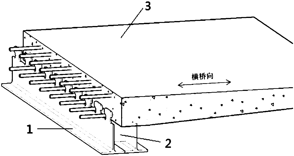
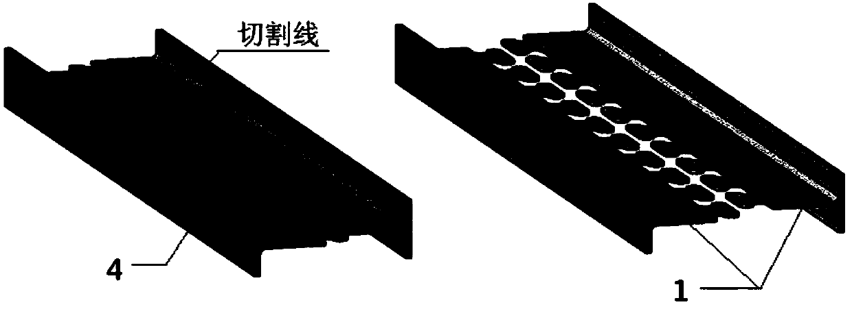
The invention provides a low groove-type steel and concrete composite beam. The composite beam comprises at least two T-shaped steel beams and a bridge deck slab arranged on the T-shaped steel beams and perpendicularly connected with webs of the T-shaped steel beams, wherein the steel wing edges of every two adjacent T-shaped steel beams are connected, the ends of the webs of the T-shaped steel beams are of tooth structures, and the tooth structures are located in the bridge deck slab.

Description

Technical field [0001] The present disclosure relates to the field of beam bridges, in particular to a low-height channel-shaped steel-concrete composite beam. Background technique [0002] Steel-concrete composite beam refers to a beam bridge formed by combining exposed steel beams or steel truss beams with reinforced concrete bridge decks through connectors (shear keys). Common steel-concrete composite beams are composed of I-shaped steel beams and reinforced concrete slabs. For bridges with relatively large spans and wide decks, steel-concrete composite beams with box sections are mostly used. The principle of the steel-concrete composite beam used as the main steel beam of the steel truss beam is similar to the steel-concrete composite beam of the I-beam and box-shaped steel beams, but in terms of structural performance, it has greater spanning capacity and greater overall rigidity than the first two types. , Long-span highway bridges and medium-span human bridges. Connect...

Claims


Application Information

Patent Timeline
IPC IPC(8): E01D19/12E01D2/00E01D101/26E01D101/30
CPCE01D2/00E01D19/125E01D2101/26E01D2101/30
Inventor 彭运动李铭张凯芮文建胡云天
Owner CCCC HIGHWAY CONSULTANTS
Learn More