
Cast-in-place pile and formation method thereof

A forming method and cast-in-place pile technology are applied in sheet pile wall, construction, infrastructure engineering and other directions, which can solve the problems of slow breaking speed, slow construction speed, and low construction efficiency.

Pending Publication Date: 2019-03-29
SHENZHEN POWER SUPPLY BUREAU +1
View PDF0 Cites 0 Cited by
  • Summary
  • Abstract
  • Description
  • Claims
  • Application Information

AI Technical Summary

Problems solved by technology

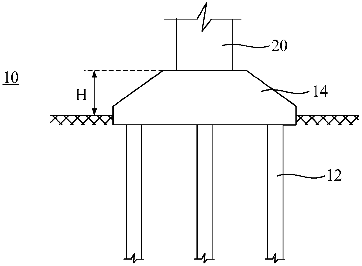
[0004] Based on this, it is necessary to solve the problem that the traditional cast-in-place pile head is broken slowly, which leads to slow overall construction speed and reduces the construction efficiency. It is necessary to provide a cast-in-place pile and its forming method that can effectively speed up the construction speed and improve the overall construction efficiency.

Method used


Image

  • Cast-in-place pile and formation method thereof
  • Cast-in-place pile and formation method thereof
  • Cast-in-place pile and formation method thereof

Examples


Embodiment Construction

[0042] In order to facilitate the understanding of the present invention, the present invention will be described more fully below with reference to the associated drawings. Preferred embodiments of the invention are shown in the accompanying drawings. However, the present invention can be embodied in many different forms and is not limited to the embodiments described herein. On the contrary, these embodiments are provided to make the understanding of the disclosure of the present invention more thorough and comprehensive.

[0043] Unless otherwise defined, all technical and scientific terms used herein have the same meaning as commonly understood by one of ordinary skill in the technical field of the invention. The terms used herein in the description of the present invention are for the purpose of describing specific embodiments only, and are not intended to limit the present invention. As used herein, the term "or / and" includes any and all combinations of one or more of ...


PUM


Abstract

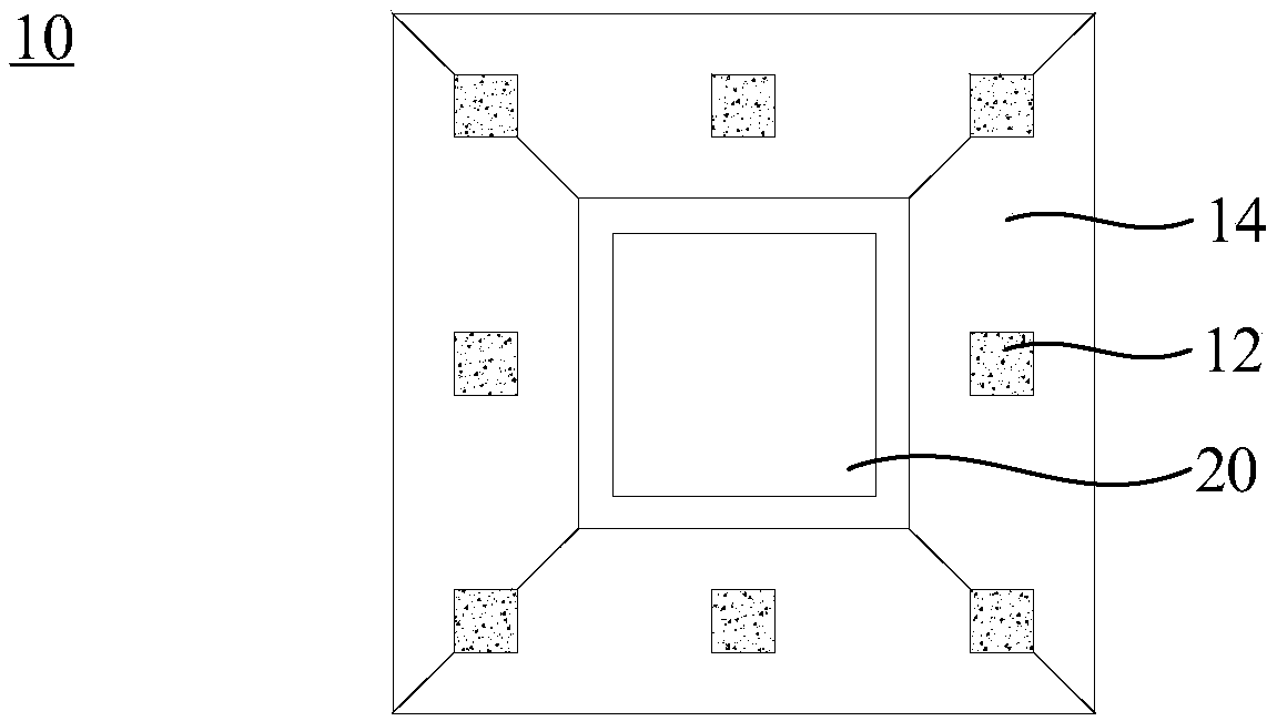
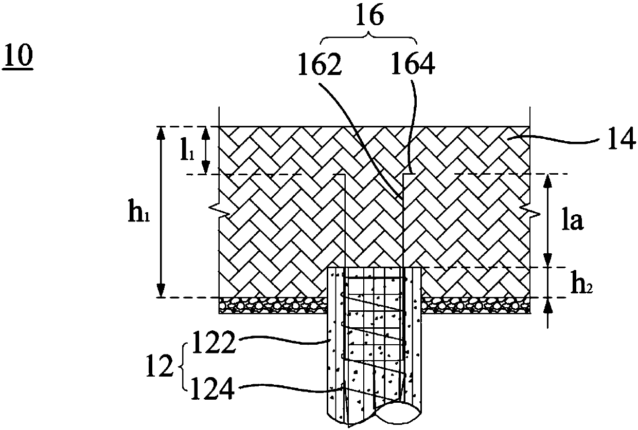
The invention relates to a cast-in-place pile. The cast-in-place pile comprises a base pile body, a bearing table and multiple connectors or multiple connectors and multiple fixing parts; the bearingtable is connected with the base pile body, the bearing table is also connected with the base pile body through the connectors or the connectors and the fixing plates, so that the connection strengthof the base pile body and the bearing table is guaranteed, in this way, detachment of a pile head is not needed, the step of detaching the pile head is omitted, the method is simple and easy to implement, the whole construction speed is effectively increased, and the construction efficiency is improved. The invention further relates to a formation method of the cast-in-place pile.

Description

technical field [0001] The invention relates to the technical field of construction pile foundation engineering, in particular to a cast-in-place pile and a forming method thereof. Background technique [0002] Concrete pouring pile is a structure often used in civil construction and foundation construction to improve the bearing capacity of the foundation. It is widely used in high-rise buildings, bridges and some areas with poor ground resistance. However, during the casting process of the grouted column, the concrete at the top of the pile will be mixed with the mud in the pile hole, and the strength is very low, which cannot reach the design strength of the pile body. Therefore, usually this part of the concrete needs to be cut off . [0003] The traditional pile head is broken manually. Because the concrete and steel bars at the pile head are solidified together, the connection strength is high, and it is necessary to prevent the steel bars at the pile head from being ...

Claims


Application Information

Patent Timeline
IPC IPC(8): E02D27/12E02D5/34
CPCE02D5/34E02D27/12
Inventor 向真师人杰王晨张成巍王德弘鞠彦忠马一丹艾精文吕启深
Owner SHENZHEN POWER SUPPLY BUREAU
Learn More