
Walking beam type oil pump additionally provided with speed increaser to adjust jig frequency

A technology of beam pumping unit and speed increaser, which is applied in the fields of exploitation fluid, wellbore/well parts, earthwork drilling and production, etc., and can solve problems such as difficult adjustment of pumping strokes, large installed power of motor, high starting current, etc. , to achieve significant energy-saving effects, increase torque, and reduce power consumption

Inactive Publication Date: 2019-03-29
潜江市尚娟贸易有限公司
View PDF0 Cites 1 Cited by
  • Summary
  • Abstract
  • Description
  • Claims
  • Application Information

AI Technical Summary

Problems solved by technology

[0002] Known oil pumping equipment, especially the beam pumping unit accounts for more than 90% of all kinds of oil pumping units in oil extraction, but this oil pumping equipment has a large motor installed power, high starting current, large energy consumption, and oil pumping equipment. Difficulty in adjusting the number of strokes. Other improved pumping units mostly use variable frequency speed regulation or double reducers to adjust the number of strokes. The defects are similar to those of the above-mentioned pumping equipment. So far there is no new technology to break through this problem.

Method used


Image

  • Walking beam type oil pump additionally provided with speed increaser to adjust jig frequency

Examples


Embodiment Construction

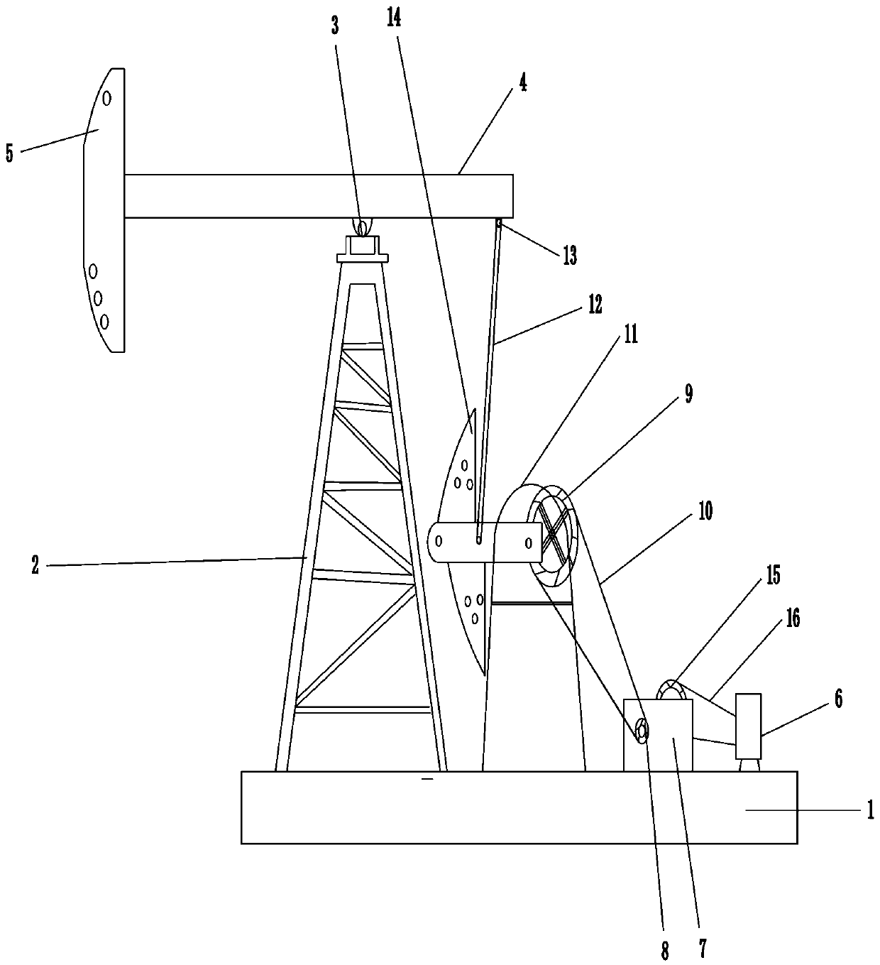
[0009] according to figure 1 As shown in the beam pumping unit of the present invention that adjusts stroke times by adding a speed increaser, a base 1 is provided, the left side of the base 1 is connected to the bracket 2, the top of the bracket 2 is connected to the central bearing assembly 3, and the central bearing assembly 3 is connected to the The beam 4, the left end of the beam 4 is connected to the donkey head 5, the right part is connected to the bearing 13, the lower end of the bearing 13 is connected to the connecting rod 12, the right part of the base 1 is connected to the reduction box 11, the speed increaser 7 and the motor 6; the motor 6 is connected to the output belt pulley Small belt 16, the other end of the small belt 16 is connected to the input pulley 15, the speed increaser 7 is connected to the output pulley 8, the output pulley 8 is connected to the large belt 10, the other end of the large belt 10 is connected to the large pulley 9, and the large pulle...


PUM


Abstract

The invention relates to a walking beam type oil pump additionally provided with a speed increaser to adjust the jig frequency. The left side of a base is connected with a bracket, the right side of the base is connected with a reduction gearbox, the speed increaser and a motor, the top of the bracket is connected with a central bearing assembly, the central bearing assembly is connected with a walking beam, the left end of the walking beam is connected with a horsehead, and the right side of the walking beam is connected with a bearing; the lower end of the bearing is connected with a connecting rod, an output belt pulley is connected with a small belt, the other end of the small belt is connected with the input belt pulley, the speed increaser is connected with the output belt pulley, and the output belt pulley is connected with a large belt; the other end of the large belt is connected with a large belt pulley, the large belt pulley is connected with an input shaft of the reductiongearbox, and an output shaft of the reduction gearbox is connected with a crank which is connected with the connecting rod; the motor drives the small belt, the small belt drives the input belt pulley, the speed increaser drives the output belt pulley, the output belt pulley drives the large belt, the large belt drives the large belt pulley, the large belt pulley drives the input shaft, the outputshaft drives the crank, the crank drives the connecting rod, and the connecting rod drives the walking beam to drive the horsehead to move up and down. The technology can meet different jig frequencyadjustment requirements and has an obvious power saving effect.

Description

technical field [0001] The invention relates to oil pumping equipment in the petroleum industry, in particular to a beam pumping unit for adjusting stroke times by adding a speed increaser. Background technique [0002] Known oil pumping equipment, especially beam pumping units account for more than 90% of all kinds of oil pumping units in oil extraction, but this oil pumping equipment has a large motor installed power, high starting current, large energy consumption, and oil pumping equipment. Difficulty in stroke adjustment and other defects. Most other improved pumping units use frequency conversion speed regulation or double reducers to adjust the stroke frequency. The defects are similar to the above-mentioned pumping equipment. So far, there is no new technology to break through this problem. Contents of the invention [0003] The invention provides a speed increaser with significant energy-saving effect by adding a speed increaser to adjust the stroke frequency of t...

Claims


Application Information

Patent Timeline
Patent Type & Authority Applications(China)
IPC IPC(8): E21B43/00
CPCE21B43/127
Inventor 王春生
Owner 潜江市尚娟贸易有限公司
Learn More