Judgment method for regeneration time of exhaust particulate filter of diesel engine

A particle trap and determination method technology, which is applied in the direction of electronic control of exhaust gas treatment device, diagnosis device of exhaust gas treatment device, exhaust device, etc. Issues such as risk of thermal damage to large DPFs

Active Publication Date: 2021-09-14
GUANGDONG UNIV OF TECH
View PDF8 Cites 0 Cited by
  • Summary
  • Abstract
  • Description
  • Claims
  • Application Information

AI Technical Summary

Problems solved by technology

Starting regeneration too early will shorten the DPF regeneration cycle, resulting in an increase in the energy consumed by active regeneration, while regeneration too late will increase the heat generated by the combustion of soot during regeneration, increasing the risk of thermal damage to the DPF
Some related studies have proposed that a certain vehicle mileage or working time be used as the timing of DPF regeneration. Although this method is simple, low in cost, and relatively easy to implement, due to the complex and changeable working conditions of diesel engines in actual vehicle operation, these methods are adopted The accuracy of judging the timing of regeneration is not high
Some other studies proposed to use 5% increase in fuel consumption rate of the diesel engine as the determination condition for trap regeneration under the premise of maintaining the same engine speed and output torque. This method improved the accuracy of judging the timing of regeneration, but the engine fuel consumption rate and output Torque needs to be equipped with special testing equipment to measure, which is expensive and inconvenient to use, so the application of this method has certain limitations

Method used


Image

  • Judgment method for regeneration time of exhaust particulate filter of diesel engine
  • Judgment method for regeneration time of exhaust particulate filter of diesel engine
  • Judgment method for regeneration time of exhaust particulate filter of diesel engine

Examples


Embodiment Construction

[0020] The present invention will be further described in detail below in conjunction with the accompanying drawings and specific embodiments. It should be understood that the specific embodiments described here are used to illustrate and explain the present invention, but not to limit the present invention.

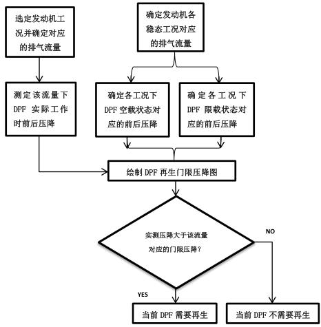
[0021] The method for judging the regeneration time of the diesel engine exhaust particulate filter of the present invention comprises the following steps:

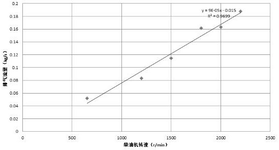
[0022] 1) Select the steady-state working conditions of the diesel engine series and measure the exhaust gas flow through the exhaust particulate filter of the diesel engine under each working condition;

[0023] 2) Determine the front-to-back pressure drop corresponding to the exhaust flow of the diesel engine exhaust particulate filter under the no-load and limited-load states under different working conditions;

[0024] 3) Draw the DPF regeneration threshold pressure drop diagram according to the obtained pressu...


PUM


Abstract

The invention relates to a method for judging the regeneration time of a diesel engine exhaust particle trap. It includes the following steps: 1) Select the steady-state working conditions of the diesel engine series and measure the exhaust gas flow through the DPF under each working condition; 2) Determine the front-to-back pressure drop corresponding to the exhaust flow of the DPF under no-load and load-limiting conditions under different working conditions ; 3) Draw the DPF regeneration threshold pressure drop diagram according to the obtained DPF load-limited state corresponding pressure drop value, and correct the drawn threshold pressure drop diagram to obtain the final DPF regeneration threshold pressure drop diagram; 4) In the selected Under the steady-state working condition of the diesel engine, first determine the exhaust flow corresponding to the working condition, and compare the actual measured pressure drop before and after the DPF with the threshold pressure drop corresponding to the flow in the threshold pressure drop diagram; 5) judge the measured DPF Whether the front-to-back pressure drop is greater than the corresponding threshold pressure drop, and then determine whether the current DPF state needs to be regenerated. The invention can more accurately determine the regeneration timing of the DPF and promote the timely regeneration of the DPF.

Description

technical field [0001] The invention relates to the technical field of post-treatment of diesel exhaust gas, in particular to a method for judging the regeneration time of a diesel exhaust particle filter, and belongs to an innovative technology for judging the regeneration time of a diesel exhaust particle filter. Background technique [0002] There are three main types of exhaust particulate matter from diesel engines: carbon particles (Soot), surface-adsorbed organic soluble matter (Soluble organic fractions, SOF for short) particles, and sulfate particles. Diesel engine exhaust particles are mostly composed of Soot and SOF particles. Diesel Exhaust Particulate Filter (DPF) is a particulate filter installed in the exhaust pipeline of a diesel engine, which captures particulate matter in the exhaust to achieve the purpose of purifying the exhaust. When the diesel engine exhaust flows through the DPF, the particulates in the exhaust are captured by the DPF through intercep...

Claims


Application Information

Patent Timeline
Patent Type & Authority Patents(China)
IPC IPC(8): F01N3/023F01N9/00F01N11/00
CPCF01N3/023F01N9/002F01N11/00Y02T10/40
Inventor 彭美春李继龙王海龙黎育雷张伟伦
Owner GUANGDONG UNIV OF TECH
Why Eureka
Try Eureka