
Detachable solar cell LED road lamp

A technology of LED road lights and solar cells, applied in circuit layout, electric light source, energy-saving lighting, etc., can solve the problems of reducing the safety performance of the lampshade, increasing the difficulty of production, and damage of the lampshade, so as to avoid perching or staying, reduce production difficulty, good sealing effect

Pending Publication Date: 2019-03-29
汉中市八度阳光科技有限公司
View PDF12 Cites 0 Cited by
  • Summary
  • Abstract
  • Description
  • Claims
  • Application Information

AI Technical Summary

Problems solved by technology

[0002] Solar battery LED road light is a lamp used for road lighting. Its power source is powered by solar power, which has the effect of saving energy, and can also illuminate the edge of the road to supplement light for people; the existing There are certain disadvantages in the use of solar cell LED road lights. First of all, the light poles used in the existing LED road lights are usually integrated. Because the height required by the street lights is relatively high, the light poles used are also relatively long, giving The transportation has brought a lot of trouble, and it has also increased the difficulty of production. Secondly, there are often birds perched and staying on the lampshade, and it is easy to leave feces on the lampshade. The feces are very corrosive and easy to damage the lampshade. damage, and birds perched on it will also increase the load-bearing of the lampshade, reduce the safety performance of the lampshade, and bring certain adverse effects to the actual use. Therefore, we propose a detachable solar battery LED road light

Method used


Image

  • Detachable solar cell LED road lamp
  • Detachable solar cell LED road lamp
  • Detachable solar cell LED road lamp

Examples


Embodiment Construction

[0019] In order to make the technical means, creative features, goals and effects achieved by the present invention easy to understand, the present invention will be further described below in conjunction with specific embodiments.

[0020] In the description of the present invention, it should be noted that the terms "upper", "lower", "inner", "outer", "front end", "rear end", "both ends", "one end", "another end" The orientation or positional relationship indicated by etc. is based on the orientation or positional relationship shown in the drawings, and is only for the convenience of describing the present invention and simplifying the description, rather than indicating or implying that the referred device or element must have a specific orientation, use a specific Azimuth configuration and operation, therefore, should not be construed as limiting the invention. In addition, the terms "first" and "second" are used for descriptive purposes only, and should not be understood ...


PUM


Abstract

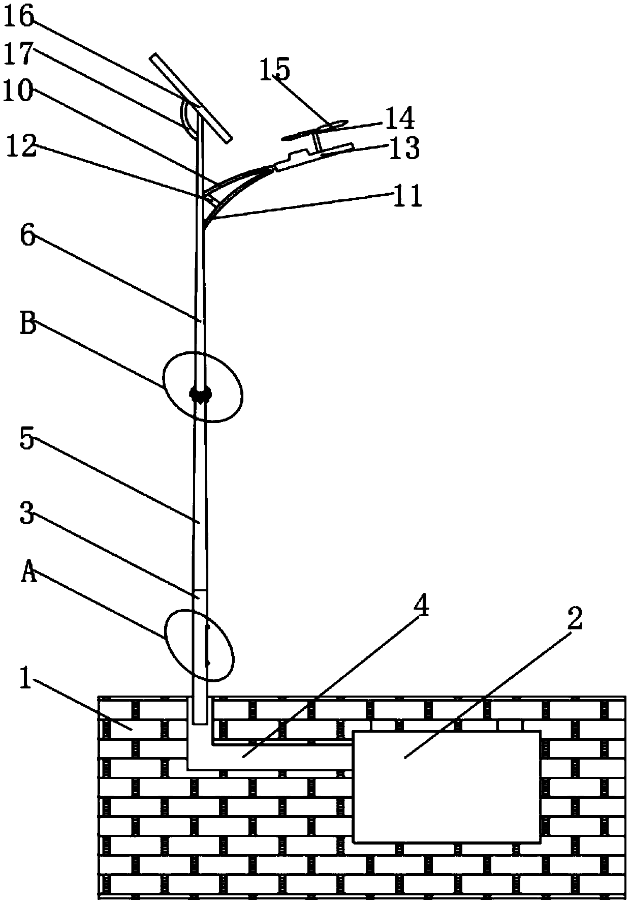
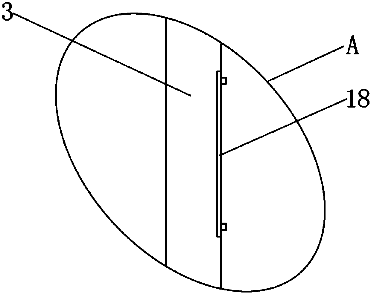
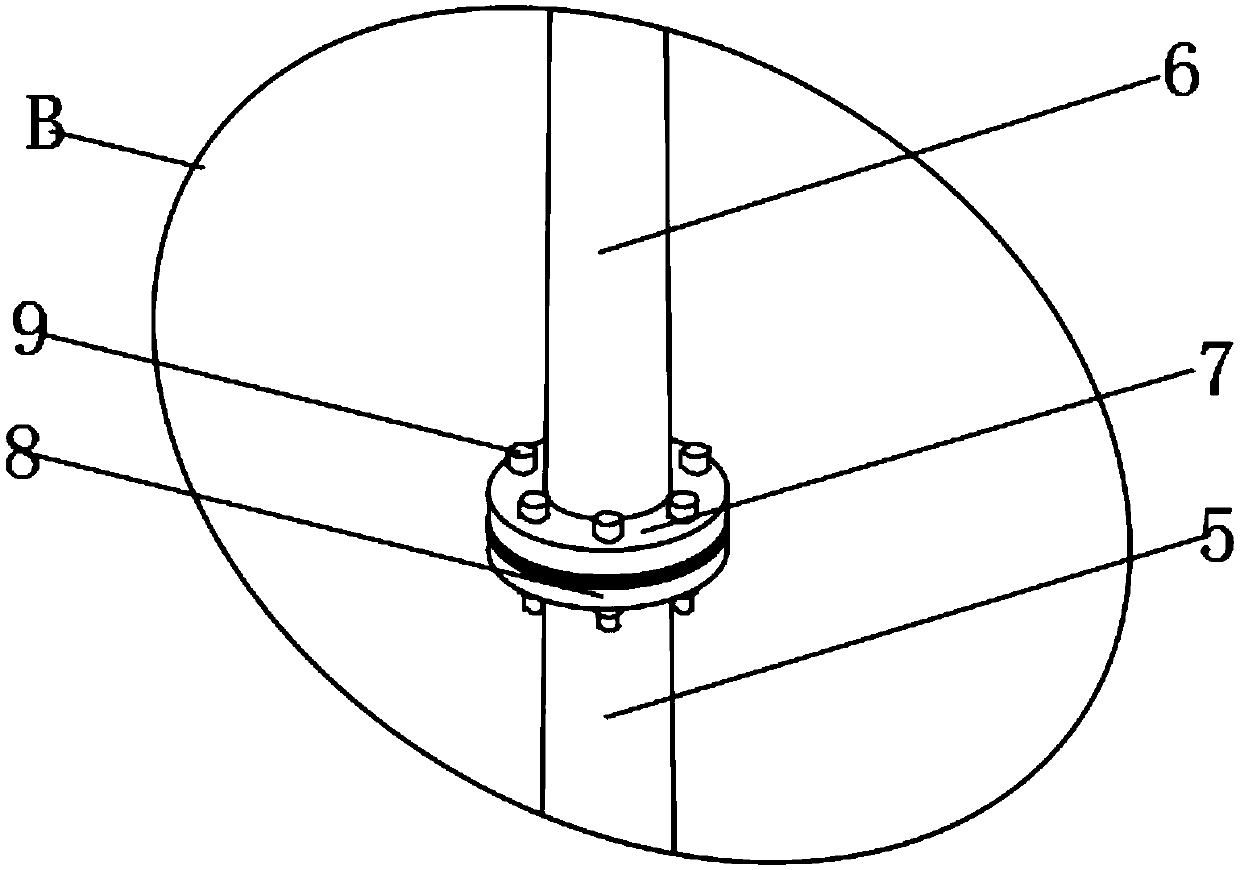
The invention discloses a detachable solar cell LED road lamp which comprises a ground, a buried box and an overhaul rod. The buried box is arranged at the lower portion of the ground. The overhaul rod is arranged at the upper portion of the ground. A wire pipe is arranged between the overhaul rod and the buried box, a main rod is connected to one end of the overhaul rod, a supporting rod is arranged at the upper portion of the main rod, an upper flange is arranged at the top end of the main rod, a lower flange sleeves the position, close to the lower end, of the exterior of the supporting rod, and a connecting screw is arranged between the upper flange and the lower flange. According to the detachable solar cell LED road lamp, by arranging the upper flange, the lower flange and a windmill, firstly, the whole lamp pole can be divided into the main rod and the supporting rod, on one hand, transporting is facilitated, on the other hand, the production difficulty is lowered, secondly, thephenomenon that bird droppings corrode a lampshade can be reduced, meanwhile, the phenomenon that the pressure of the lampshade is increased by a bird's nest can be avoided, and the better using prospect is achieved.

Description

technical field [0001] The invention relates to the field of road lamps, in particular to a detachable solar cell LED road lamp. Background technique [0002] Solar battery LED road light is a lamp used for road lighting. Its power source is powered by solar power, which has the effect of saving energy, and can also illuminate the edge of the road to supplement light for people; the existing There are certain disadvantages in the use of solar battery LED road lights. First of all, the light poles used in the existing LED road lights are usually integrated. Because the height required by the street lights is relatively high, the light poles used are also relatively long. The transportation has brought a lot of trouble, and it has also increased the difficulty of production. Secondly, there are often birds perching and staying on the lampshade, and it is easy to leave feces on the lampshade. The feces are very corrosive and easy to cause damage to the lampshade. Damage, and b...

Claims


Application Information

Patent Timeline
Patent Type & Authority Applications(China)
IPC IPC(8): F21S9/03F21V21/10A01M29/06F21V23/00F21W131/103F21Y115/10
CPCA01M29/06F21S9/035F21V21/10F21V23/003F21W2131/103Y02B20/72
Inventor 刘一锋
Owner 汉中市八度阳光科技有限公司
Learn More