Display panel for joint and manufacturing method thereof

A technology of a display panel and a manufacturing method, which are applied to emergency protection circuit devices, electrical components, diodes, etc. for limiting overcurrent/overvoltage, can solve the problem of reducing reliability and production yield, reducing production yield, thin film components Damage and other problems, to achieve the effect of improving the production yield, reducing the probability of disconnection, and protecting the components

Active Publication Date: 2019-03-29
AU OPTRONICS CORP
View PDF4 Cites 6 Cited by
  • Summary
  • Abstract
  • Description
  • Claims
  • Application Information

AI Technical Summary

Problems solved by technology

However, in the existing manufacturing process, after the thin film manufacturing process on the display surface is completed, the driving circuit manufacturing process is performed on the back side, which will damage the thin film components on the display surface, reduce the production yield and increase the cost.
In addition, the process level of making the wire structure on the side wall of the display panel is relatively high, and it is easy to produce uneven thickness and cause disconnection, which will cause signal failure, reduce reliability and production yield

Method used


Image

  • Display panel for joint and manufacturing method thereof
  • Display panel for joint and manufacturing method thereof
  • Display panel for joint and manufacturing method thereof

Examples


Embodiment Construction

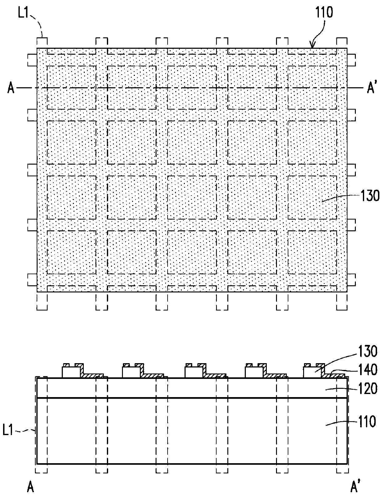
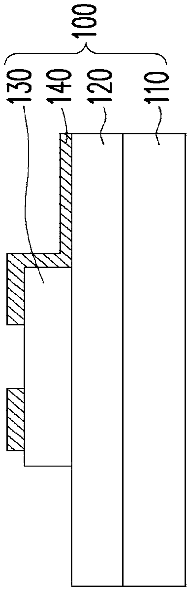
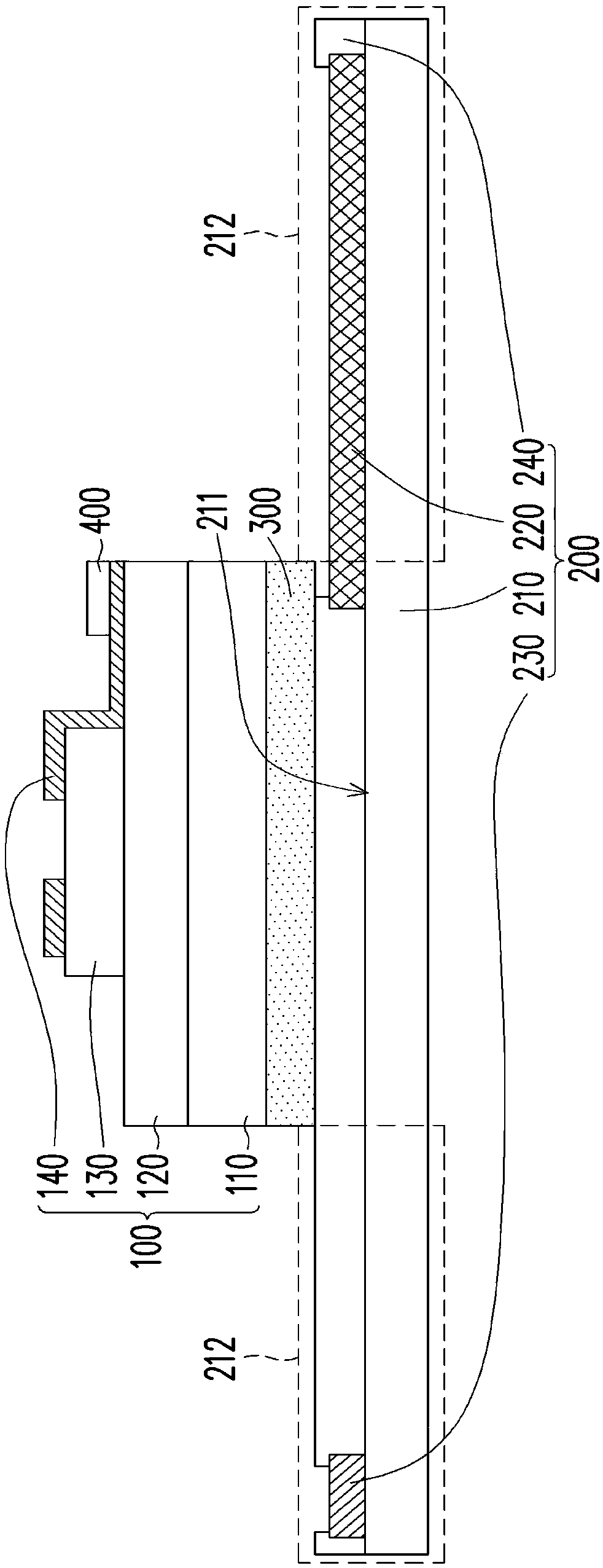
[0036] In the drawings, the thickness of layers, films, panels, regions, etc., are exaggerated for clarity. Throughout the specification, the same reference numerals denote the same elements. It will be understood that when an element such as a layer, film, region, or substrate is referred to as being "on" or "connected to" another element, it can be directly on or connected to the other element, or Intermediate elements may also be present. In contrast, when an element is referred to as being "directly on" or "directly connected to" another element, there are no intervening elements present. As used herein, "connected" may refer to physical and / or electrical connection. Furthermore, "electrically connected" or "coupled" may mean that other elements exist between two elements.

[0037] It should be understood that although the terms "first", "second", "third" etc. may be used herein to describe various elements, components, regions, layers and / or sections, these elements, c...


PUM


Abstract

Provided is a display panel for joint, comprising a first substrate, a second substrate, a bonding layer disposed between the first substrate and the second substrate, and a conductive rubber layer disposed on the first substrate. The second substrate comprises a first wire structure and a second wire structure, which are disposed on the surface of the second substrate. The first substrate appliesto the second substrate. The first wire structure is electrically connected to the conductive rubber layer. The part of the second substrate, not overlapping the first substrate is defined with a plurality of protruding parts. A part of the first wire structure is positioned in one of the protruding parts. The second wire structure is positioned in another of the protruding parts. One of the protruding parts is bended and is jointed to the first substrate and to the sidewall of the first substrate. The other of the protruding part turns its back to the first substrate and is bent. The invention also provides a manufacturing method for the display panel for joint.

Description

technical field [0001] The present invention relates to a display panel and a manufacturing method thereof, and in particular to a splicing display panel and a manufacturing method thereof. Background technique [0002] In recent years, in order to maximize the screen size, display panels with narrow borders are more and more widely used in various devices. In order to realize a large-size display device, the concept and application of splicing multiple display panels has gradually emerged. However, when multiple display panels are spliced ​​into a large display device, the frame width of the display panels often causes discontinuity in the display images at the junctions between adjacent display panels. [0003] In the existing narrow-frame or frameless display panels, the drive control circuit is fabricated on the back of the display panel (for example: the back of the display surface), and then a wire structure is formed on the side of the display panel to conduct the di...

Claims


Application Information

Patent Timeline
Patent Type & Authority Applications(China)
IPC IPC(8): H01L27/32H01L27/15
CPCH01L27/0207H01L27/0255H01L27/0288H01L27/0296H02H9/02H01L2224/18H02H9/046
Inventor 黄婉真王脩华王薰仪刘品妙郑君丞
Owner AU OPTRONICS CORP
Why Eureka
Try Eureka