Lithium battery negative electrode current collecting method

A technology of lithium battery and negative electrode, which is applied in the field of lithium battery negative electrode and its current collection, can solve the problems of unable to exert the energy density of lithium battery, restrict the development of lithium metal battery, reduce the energy density of battery, etc., and achieve good current collection effect, Large industrial and commercial application value, the effect of increasing energy density

Inactive Publication Date: 2019-03-29
GUIZHOU MEILING POWER SUPPLY CO LTD
View PDF2 Cites 7 Cited by
  • Summary
  • Abstract
  • Description
  • Claims
  • Application Information

AI Technical Summary

Problems solved by technology

In addition, as an inactive material, the current collector occupies a certain mass ratio in the battery. The higher the mass ratio of the current collector in the battery, the energy density of the battery is bound to be reduced, and the advantages of high energy density of lithium batteries cannot be exerted.
At present, the current collection method commonly u

Method used


Image

  • Lithium battery negative electrode current collecting method
  • Lithium battery negative electrode current collecting method
  • Lithium battery negative electrode current collecting method

Examples


Example Embodiment

[0020] Example 1:

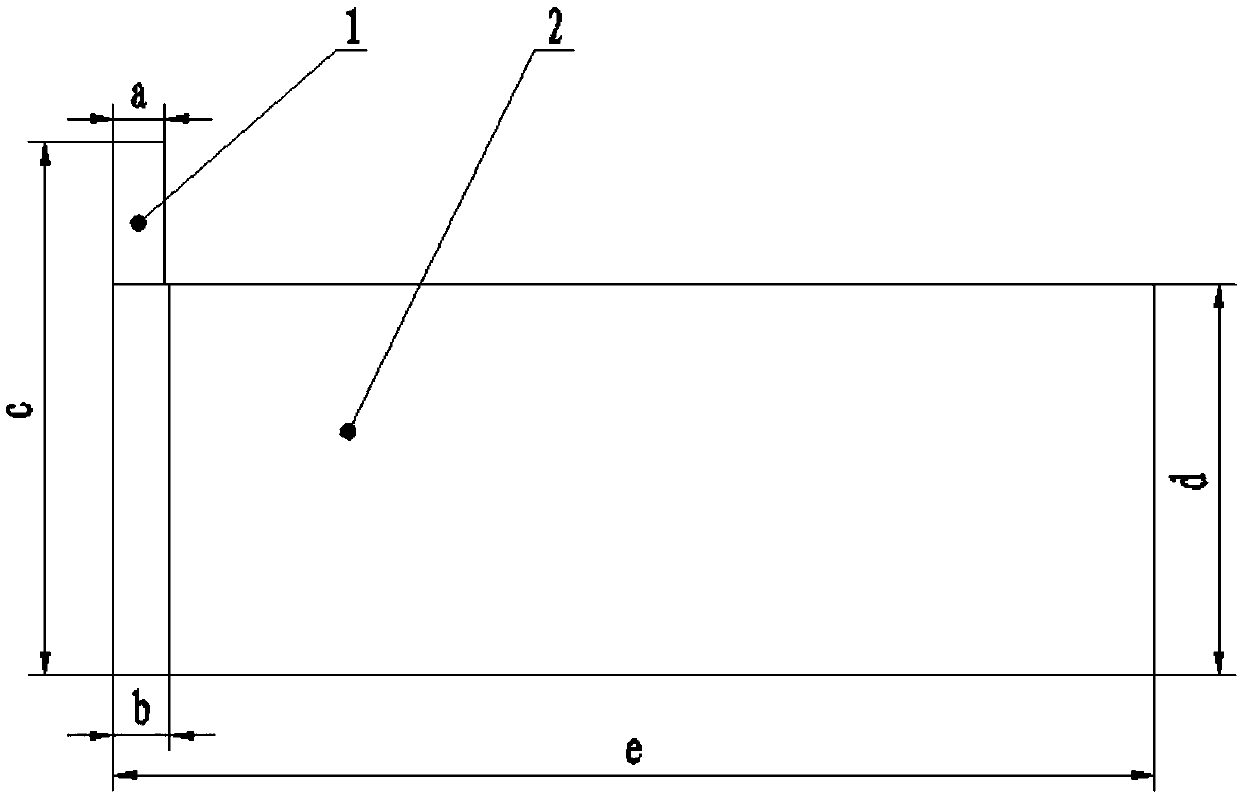
[0021] Such as figure 1 As shown, a nickel strip with a thickness of 0.08mm is selected as the tab, a width a of 10mm, and a length c of 75mm; a metal lithium tape with a thickness of 0.1mm is selected as the negative electrode, the width d is 58mm, and the length e is 450mm, which wraps the tab The part length b is 12mm. Use a hydraulic press to flatten the wrapped part under a pressure of 10 MPa, so that the lithium belt and the nickel strip are tightly combined to obtain a negative electrode with good current collection effect.

[0022] A sulfur-carbon composite material with a sulfur content of 70% is used as the positive electrode, Celgard2325 film is used as the diaphragm, and the aluminum-plastic packaging film is used to inject bistrifluoromethyl xanthimide lithium-based organic electrolyte to form a battery after sealing.

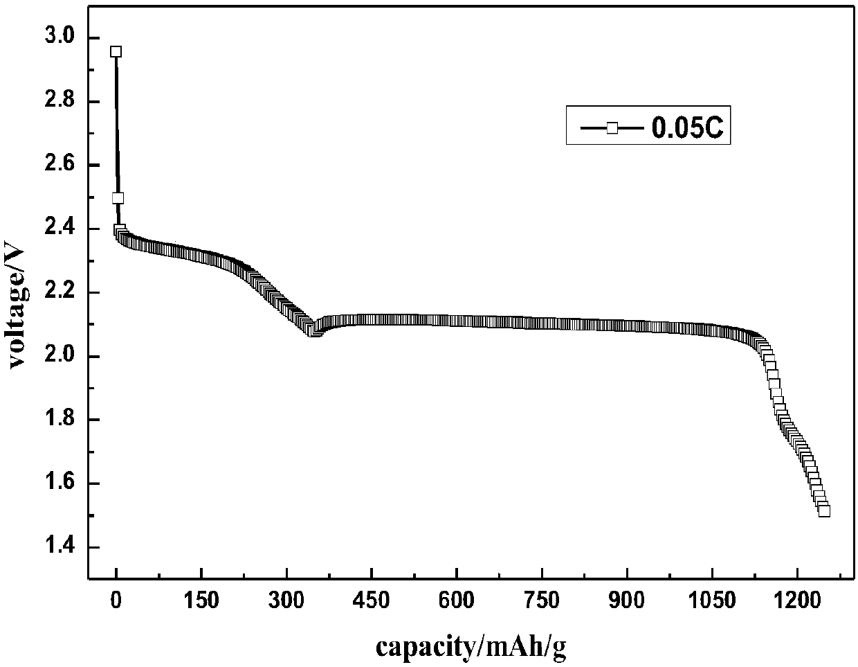
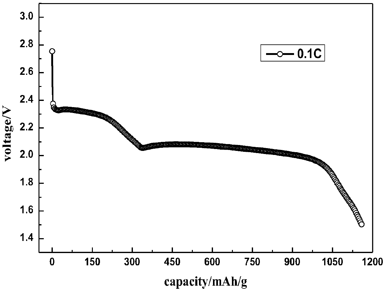
[0023] The assembled battery is discharged at a rate of 0.05C and 0.1C, the discharge cut-off voltage is 1.5V, and the discharge cur...

Example Embodiment

[0025] Example 2:

[0026] Such as figure 1 As shown, a nickel strip with a thickness of 0.1mm is selected as the tab, the width a is 6mm, and the length c is 60mm; a metal lithium tape with a thickness of 0.12mm is selected as the negative electrode, the width d is 45mm, and the length e is 450mm, which wraps the tab The part length b is 8mm. Use a hydraulic press to flatten the wrapped part under a pressure of 8MPa, so that the lithium belt and the nickel strip are tightly combined to obtain a negative electrode with good current collection effect.

[0027] A sulfur-carbon composite material with 80% sulfur content is used as the positive electrode, Celgard2325 film is used as the diaphragm, and the aluminum-plastic packaging film is used to inject bistrifluoromethylxanthimide lithium-based organic electrolyte, and the battery is formed after sealing. The specific discharge capacity of the battery is 1327.5mAh / g at a rate of 0.05C, and the specific energy of the battery is calcu...


PUM

PropertyMeasurementUnit
Thicknessaaaaaaaaaa
Widthaaaaaaaaaa
Widthaaaaaaaaaa

Abstract

The invention discloses a lithium battery negative electrode and a lithium battery negative electrode current collecting method. The lithium battery negative electrode includes a lug (1) and a metal negative electrode (2). Steps of lithium battery negative electrode current collecting comprise: placing the lug (1) on one side of the metal negative electrode (2), wherein the lug (1) is wrapped by the metal negative electrode (2), using a press machine to planish the part of the lug (1), wrapped by the metal negative electrode (2) under certain pressure, to obtain the negative electrode. The method has relatively simple operation, and is low in cost and easy in realization. On the premise of ensuring current collecting effect, proportion of non-active substances in a battery is effectively reduced, thereby facilitating improvement of energy density of the lithium battery. The method and has large industrial and commercial application value.

Description

technical field [0001] The invention belongs to the technical field of lithium batteries, in particular to a lithium battery negative electrode and a current collecting method thereof. Background technique [0002] Lithium batteries can be divided into lithium metal batteries and lithium ion batteries. The lithium batteries involved in the present invention refer to lithium metal batteries. Lithium metal batteries generally use manganese dioxide, iodine, carbon fluoride, sulfur or sulfur-containing composite materials as the positive electrode, metal lithium or its alloy metal as the negative electrode material, and a battery using a non-aqueous electrolyte solution. Currently commercialized lithium metal batteries are mainly lithium primary batteries, including lithium iodine batteries, lithium manganese dioxide batteries, lithium thionyl chloride batteries, lithium fluoride carbon batteries, lithium sulfur dioxide batteries, etc., mainly used in cardiac pacemakers , calcu...

Claims


Application Information

Patent Timeline
IPC IPC(8): H01M2/26H01M10/052H01M10/058H01M50/531
CPCH01M10/052H01M10/058H01M50/531Y02E60/10Y02P70/50
Inventor 王振
Owner GUIZHOU MEILING POWER SUPPLY CO LTD
Why Eureka
Try Eureka