
Permanent magnet synchronous motor rotor skewed pole structure and assembly method

A technology for permanent magnet synchronous motors and rotors, applied in the direction of magnetic circuit shape/style/structure, electric components, electromechanical devices, etc., can solve problems such as low production efficiency and high cost, and achieve improved production efficiency, reduced noise and vibration, and reduced Effect of cogging torque

Pending Publication Date: 2019-03-29
菲仕绿能科技(北京)有限公司
View PDF0 Cites 2 Cited by
  • Summary
  • Abstract
  • Description
  • Claims
  • Application Information

AI Technical Summary

Problems solved by technology

[0003] At present, most of the oblique pole structures of the rotors produced are mainly two-stage oblique poles. The main problem is that the multi-stage oblique pole structure requires several sets of different punching sheets, which leads to the need for multiple sets of punching dies, high cost and low production efficiency.

Method used


Image

  • Permanent magnet synchronous motor rotor skewed pole structure and assembly method
  • Permanent magnet synchronous motor rotor skewed pole structure and assembly method
  • Permanent magnet synchronous motor rotor skewed pole structure and assembly method

Examples


Embodiment Construction

[0026] The following is based on Figure 1 to Figure 3 The specific embodiment of the present invention is further described:

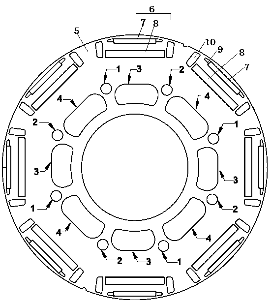
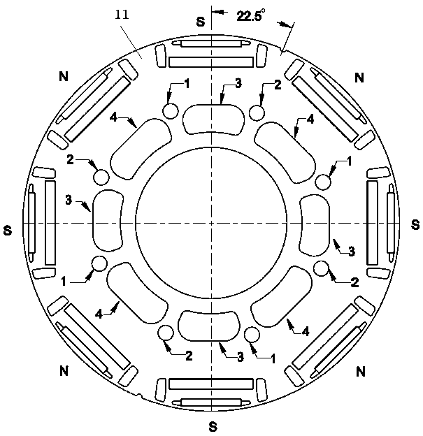
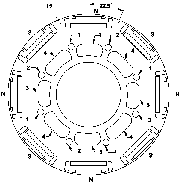
[0027] see Figure 1 to Figure 3 , a permanent magnet synchronous motor rotor skew structure, including a first rotor module 11 (such as figure 2 ) and the second rotor module 12 (as image 3 ), the first rotor module 11 and the second rotor module 12 are composed of a plurality of identical rotor punches 5 (such as figure 1 ) stacked on top of each other. see figure 1 A plurality of through holes 1 and a plurality of through holes 2 are axially opened on the circumferential end surface of the rotor punching plate 5, and the centers of the plurality of through holes 1 and the plurality of through holes 2 are located on the same circle , the circumferential end surface of the rotor punching plate 5 is axially provided with a plurality of weight removal holes 1 3 and a plurality of weight removal holes 2 4, and the centers of the plurality of weig...


PUM


Abstract

The invention discloses a permanent magnet synchronous motor rotor skewed pole structure and an assembly method. The structure comprises first rotor modules and a second rotor module. The first rotormodules and the second rotor module comprise multiple identical rotor punching sheets. A plurality of through holes I and through holes II are arranged in the axial directions of the rotor punching sheets. A plurality of de-weighting holes I and de-weighting holes II are arranged in the axial directions of the rotor punching sheets. The through holes I, the de-weighting holes I, the through holesII and the de-weighting holes II are distributed clockwise in turn. S-pole steel magnets are installed in steel magnet slots right above the outer sides of the de-weighting holes I of the first rotormodules, and N-pole steel magnets are installed in steel magnet slots right above the outer sides of the de-weighting holes II. N-pole steel magnets are installed in steel magnet slots right above theouter sides of the de-weighting holes I of the second rotor module, and S-pole steel magnets are installed in steel magnet slots right above the outer sides of the de-weighting holes II. The rotor punching sheets of the same structure are adopted, and a multi-segment skewed pole structure of the rotor is realized through different assembly angles of the first rotor modules and the second rotor module. There is no need for multiple sets of punching dies. The cost is low, and the production efficiency is high.

Description

technical field [0001] The invention relates to the technical field of motors, in particular to a rotor oblique pole structure and assembly method of a permanent magnet synchronous motor. Background technique [0002] As a vital part of the motor, the rotor core is responsible for magnetic conduction and connection to the rotating shaft. As a power source for various machines, it converts electrical energy into mechanical energy. The permanent magnet will not change the magnetic strength according to the position and state of the motor, so during the operation of the circumferential direction, the magnetic poles of the magnetic steel have different attractive forces on the stator slots, and the different sizes of the attractive forces will cause the rotor to rotate during the rotation process. The torque fluctuates, which leads to vibration and noise during operation. The reduction measure is to reduce the cogging torque to reduce the noise and vibration of the motor during ...

Claims


Application Information

Patent Timeline
IPC IPC(8): H02K1/27H02K15/03
CPCH02K1/27H02K15/024H02K15/03
Inventor 林汝裕牛正蕊虞蒙盛罗宏浩
Owner 菲仕绿能科技(北京)有限公司
Learn More