Commutation control method and apparatus for power inverter

A power inverter, phase control technology, applied in control systems, motor control, electronic commutators, etc., can solve problems such as being susceptible to interference and reducing system stability, and achieve the effect of high stability

Active Publication Date: 2019-03-29
CHENGDU JOUAV AUTOMATION TECH
View PDF3 Cites 3 Cited by
  • Summary
  • Abstract
  • Description
  • Claims
  • Application Information

AI Technical Summary

Problems solved by technology

[0007] In view of this, the object of the present invention is to provide a power inverter commutation control method to solve the problems in the prior art that the working stability of the system is reduced, and it is easy to be disturbed and stop working
[000

Method used


Image

  • Commutation control method and apparatus for power inverter
  • Commutation control method and apparatus for power inverter
  • Commutation control method and apparatus for power inverter

Examples


no. 2 example

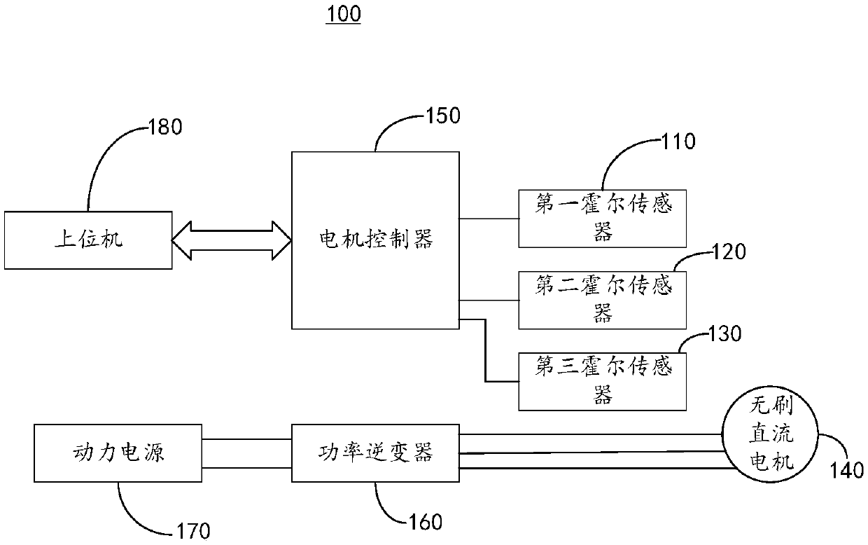
[0071] see Figure 8 , an embodiment of the present invention provides a schematic diagram of functional units of a commutation control device for a power inverter 160 . It should be noted that the basic principles and technical effects of the power inverter 160 commutation control device provided in this embodiment are the same as those of the above-mentioned embodiments. For a brief description, the parts not mentioned in the embodiments of the present invention are Reference may be made to the corresponding content in the foregoing embodiments. The power inverter 160 commutation control device includes:

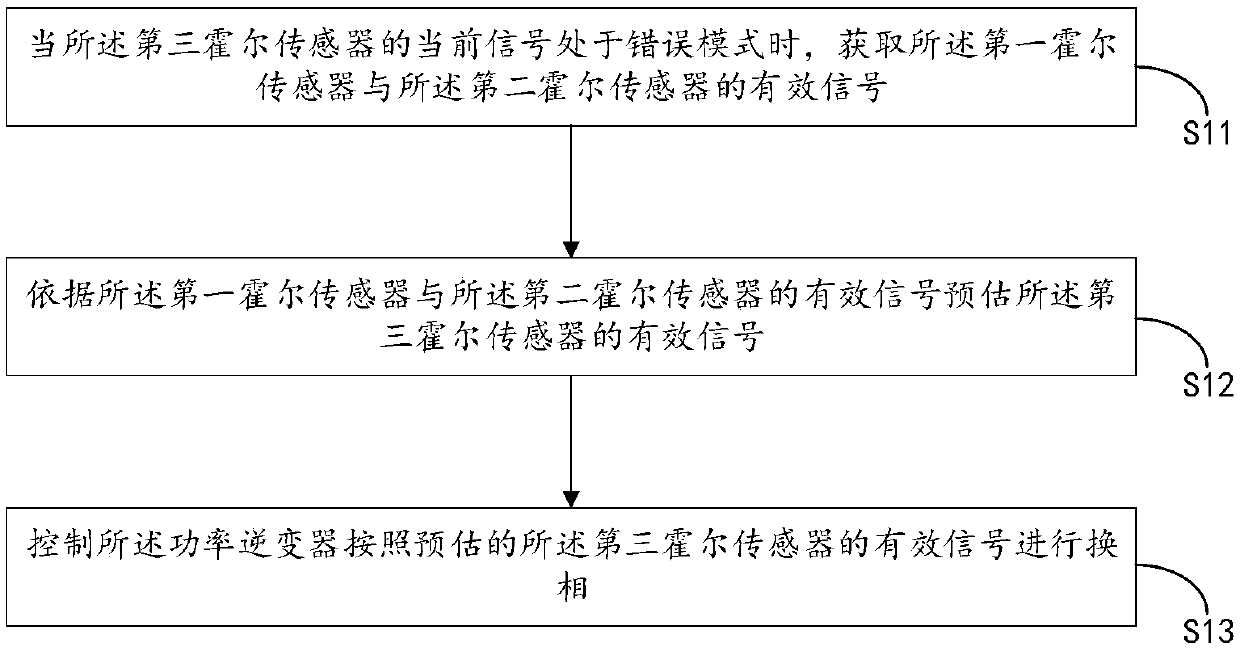
[0072] The signal acquiring unit 210 is configured to acquire valid signals of the first Hall sensor 110 and the second Hall sensor 120 when the current signal of the third Hall sensor 130 is in an error mode.

[0073] Understandably, step S11 may be executed by the signal acquisition unit 210 .

[0074] The signal estimation unit 220 is configured to estimate the effec...


PUM


Abstract

The invention provides a commutation control method and apparatus for a power inverter, and relates to the technical field of brushless direct current motors. The commutation control method and apparatus for a power inverter are characterized in that when a current signal of a third Hall sensor is in an error mode, valid signals of a first Hall sensor and a second Hall sensor are acquired; and according to the valid signals of the first Hall sensor and the second Hall sensor, the valid signal of the third Hall sensor is estimated, and the power inverter is controlled to perform commutation according to the estimated valid signal of the third Hall sensor. The commutation control method and apparatus for a power inverter have the advantages of being higher in stability of working of the system.

Description

technical field [0001] The invention relates to the technical field of brushless direct current motors, in particular to a method and device for controlling phase commutation of a power inverter. Background technique [0002] The brushless DC motor is different from the brushed motor that uses a mechanical commutation mechanism (brush), and uses an electronic commutator (power inverter) to invert DC power into three-phase AC power; the three-phase AC power synthesizes vector action On the armature winding of the motor, the driving magnetic field that drives the permanent magnet rotor of the motor to rotate is generated for time accumulation; the direction of the driving magnetic field must match the direction of the main magnetic field of the rotor permanent magnet, so it is directly or indirectly detected that the main magnetic pole of the rotor is brushless DC The key to motor drive technology. [0003] As a direct detection method for the main magnetic pole of the rotor ...

Claims


Application Information

Patent Timeline
IPC IPC(8): H02P6/16
CPCH02P6/16H02P2207/05
Inventor 刘仕伟杨建刘述超
Owner CHENGDU JOUAV AUTOMATION TECH
Why Eureka
Try Eureka