Method and device for grinding a rotationally symmetric machine part

A machine component, rotationally symmetric technology, applied in the direction of grinding machine parts, machine tools designed for grinding the rotating surface of workpieces, grinding frames, etc., can solve the problems of short life, uneven cooling of grinding positions, etc. Uniform and cooling zone, the grinding speed remains uniform, the effect of a narrow cooling zone

Inactive Publication Date: 2007-08-29
ERWIN JUNKER MASCHNINENFAB
View PDF9 Cites 0 Cited by
  • Summary
  • Abstract
  • Description
  • Claims
  • Application Information

AI Technical Summary

Problems solved by technology

thus causing uneven cooling of the grinding position
All these difficulties arise from the fact that the prior art methods have hitherto been implemented w

Method used


Image

  • Method and device for grinding a rotationally symmetric machine part
  • Method and device for grinding a rotationally symmetric machine part
  • Method and device for grinding a rotationally symmetric machine part

Examples


Embodiment Construction

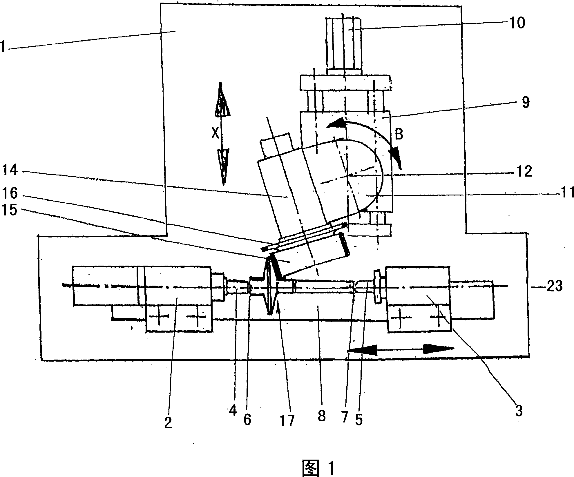
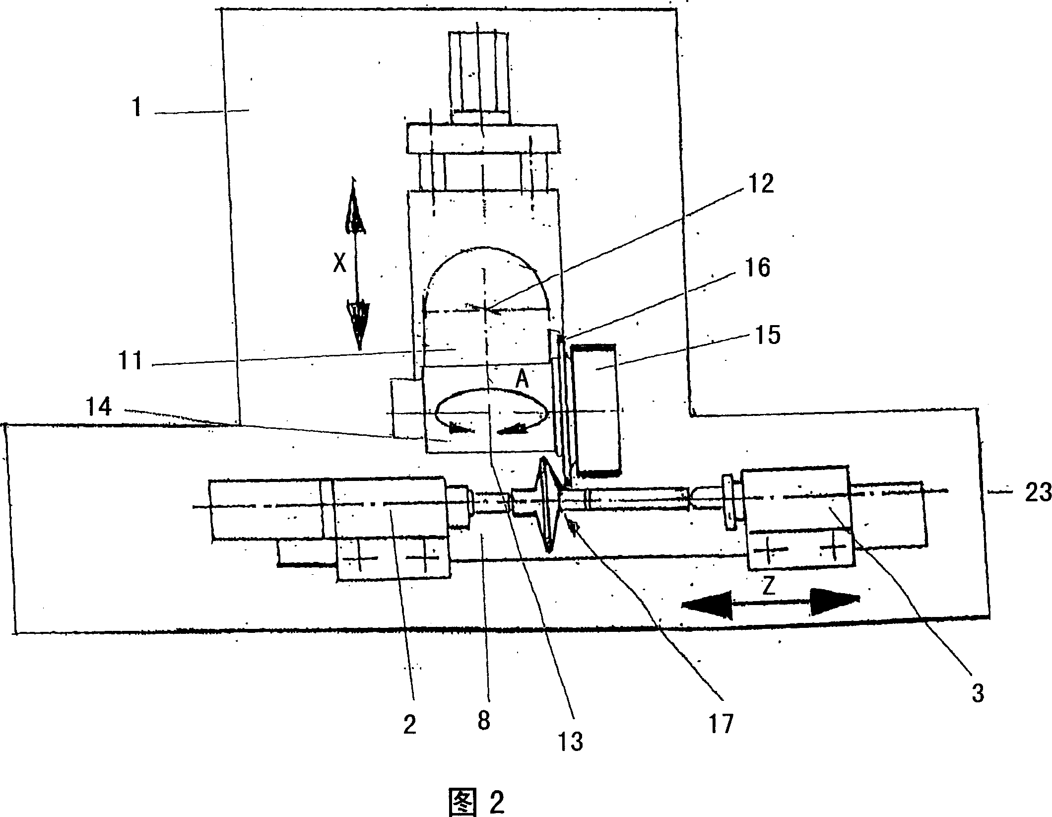
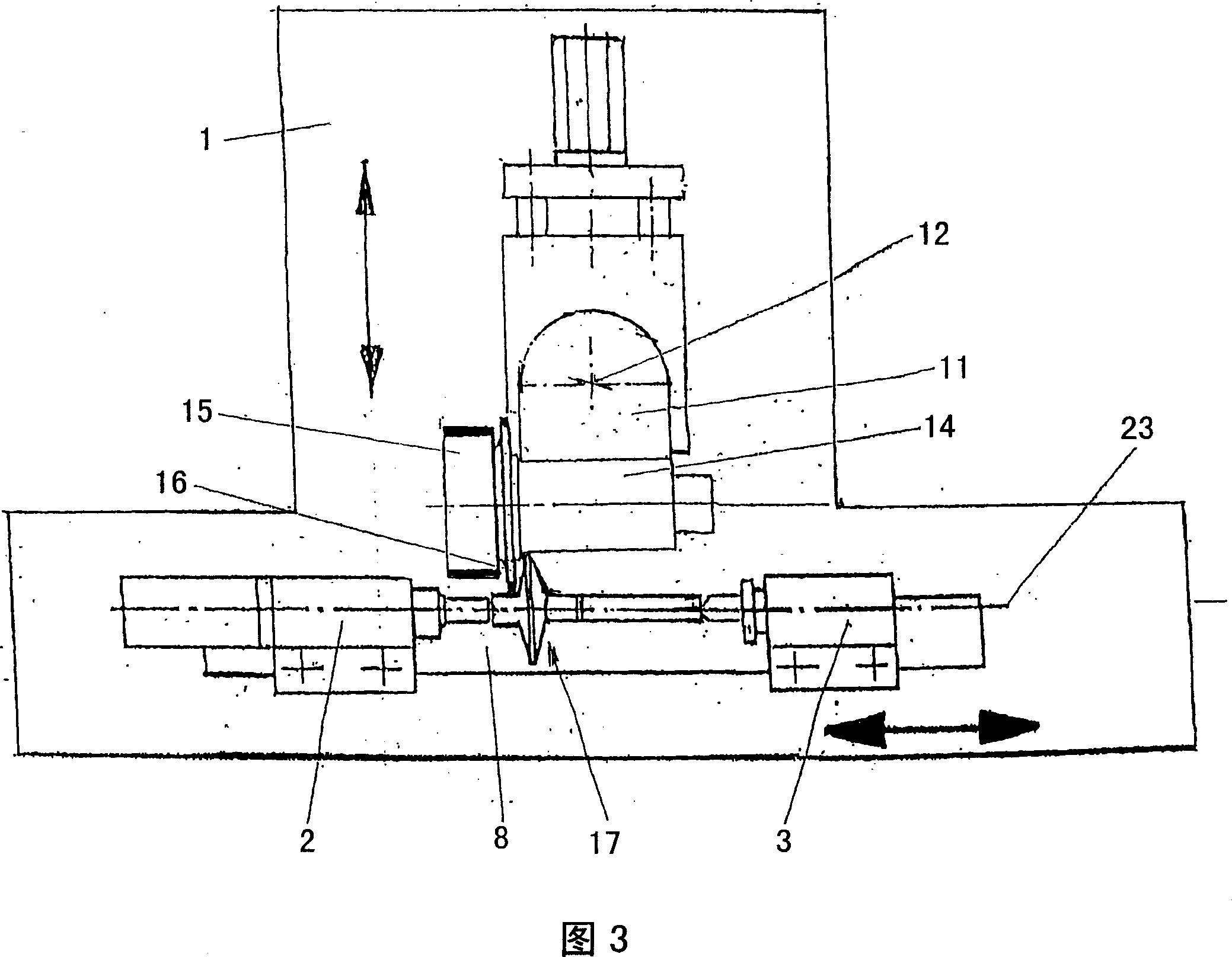
[0057] FIG. 1 shows the device according to the invention for grinding, in particular for carrying out the method according to the invention. The device shown in FIG. 1 consists of a bed 1 on which a workpiece spindle headstock 2 and a tailstock 3 are arranged. The workpiece spindle headstock 2 and tailstock 3 have conventional center sleeves (not shown in the figures) with centers 4, 5 having centers 6 and 7 on the shaft between which machine parts 17 are clamped. between. In the exemplary embodiment shown, the workpiece spindle headstock 2 and the tailstock 3 are arranged on a grinding machine table 8 which is displaceable in the longitudinal direction of the machine part 17 . After clamping, the machine part 17 , the workpiece headstock 2 and the tailstock 3 have a common longitudinal axis 23 which is the reference line on which the other parts are arranged.

[0058] FIG. 1 also schematically shows a grinding wheel spindle saddle 9 which can be advanced in a direction per...


PUM


Abstract

Disclosed are a method and a device for grinding a machine part (17) that comprises two shaft elements (18, 19) and a central element (20) having a significantly increased diameter (D). The central element (20) is provided with an effective surface (22), a portion of which is embodied in the form of a flat truncated cone (21). In order to grind the excess material (25) off the effective surface (22), the machine part (17) is clamped between pins (6, 7) that are provided with shafts (4, 5), the shaft (5) located at the tailstock (3) being supported by a steady rest (27). The machine part (17) is movable in the direction of the longitudinal axis (23) thereof. The effective surface (22) of the machine part (17) can be placed against the grinding disk (15) at the line of contact (28), vertical grinding being done by means of the cylindrical outer contour of the first grinding disk (15) such that the cutting speed is constant across the entire axial dimension of the first grinding disk (15) and a very good grinding result is obtained. The first grinding disk (15) is mounted in a floating manner on a grinding spindle (14) along with a second, narrower grinding disk (16). The second grinding disk (16) can be brought into an operating position, in which the cylindrical peripheral areas of the machine part are to be machined by means of longitudinal grinding, by swiveling the spindle (14) about two swiveling axes that are located perpendicular to each other and by displacing the grinding spindle (14) perpendicular to the longitudinal axis (23), the machine part remaining in the same clamped position. The inventive working method results in shortened cycle times while providing for a very good grinding result.

Description

technical field [0001] The invention relates to a method and a device for grinding a rotationally symmetrical machine part having two shaft parts and a middle part with an enlarged diameter between them, on which a section is formed. Conical shell-shaped active surface with a rectilinear or arcuate profile in cross-section. Background technique [0002] Such machine components are, for example, components in continuously variable transmissions used in motor vehicles. There are two machine parts with opposing active surfaces. The active surfaces thus form an approximately wedge-shaped annular space in which, for example, a chain or a belt moves back and forth between different radii depending on the mutual distance between the active surfaces. Since this type of transmission requires high machining accuracy and must transmit large rotational torques, it places high demands on the dimensional accuracy and surface quality of the machine components. This also applies to the g...

Claims


Application Information

Patent Timeline
IPC IPC(8): B24B5/14B24B41/02B24B41/06B24B27/00B24B41/04B24B5/02
CPCB24B5/14B24B41/062B24B27/0084B24B41/02B24B27/00B24B41/06
Inventor 埃尔温·容克尔
Owner ERWIN JUNKER MASCHNINENFAB
Why Eureka
Try Eureka