Intraoral saliva suction support device

A technology of a supporter and a supporting part, applied in the direction of saliva remover, etc., can solve the problems of temporomandibular joint disease, fatigue of chewing muscles, aspiration of oral mucosa, etc., to achieve a wide range of saliva suction, avoid fatigue, and continuous suction Effect

Pending Publication Date: 2019-04-02
SHANDONG UNIV QILU HOSPITAL
View PDF0 Cites 2 Cited by
  • Summary
  • Abstract
  • Description
  • Claims
  • Application Information

AI Technical Summary

Problems solved by technology

The conventional saliva suction device sucks saliva in a point-like shape on the head. In clinical application, the position needs to be constantly moved and the cooperation of an assistant is often required. The suction is mainly concentrated on the head. The inventors of the present disclosure have found that this conventional saliva suction device has large noise and may Aspiration into soft oral mucosa and damage
At the same time, according to the inventor’s oral clinical operation experience, the oral clinical operation often takes a long time, sometimes up to several hours, and the patient’s mouth opening for a long time will cause fatigue of the masticatory muscles, and even cause temporomandibular joint disorders.

Method used


Image

  • Intraoral saliva suction support device
  • Intraoral saliva suction support device
  • Intraoral saliva suction support device

Examples


Embodiment 1

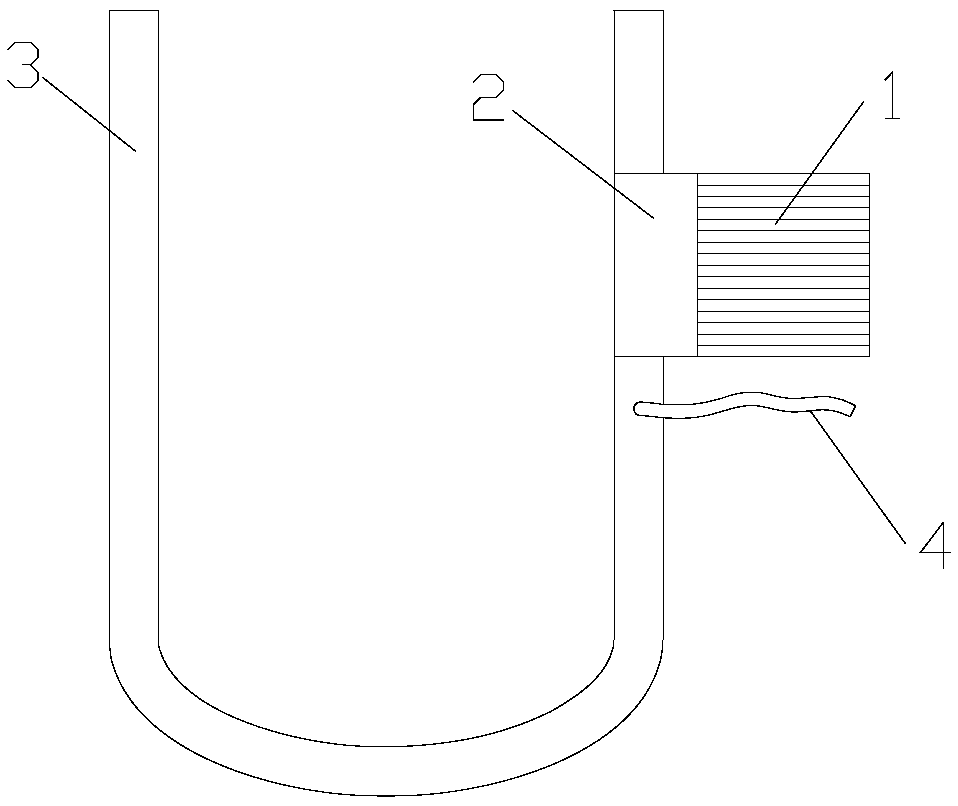
[0047] Intraoral saliva support, such as Figure 1~3 As shown, a supporter for sucking saliva in the mouth is composed of a supporting part 1, a connecting part 2 and a tube 3 for sucking saliva.

[0048] The supporting part 1 is a block structure, and the opposite surfaces of the block structure are all set as contact surfaces with the crown.

[0049] Connecting part 2 is the part that supporting part is connected with saliva suction pipe 3, and the joint of connecting part 2 and supporting part 1 and the connecting part of connecting part 2 and saliva suction pipe 3 are apart from setting distance, one side of connecting part 2 It is fixedly connected to the edge of the contact surface of the supporting part 1 .

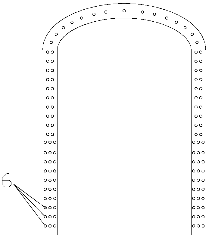
[0050] The saliva suction tube 3 is a U-shaped tube, the side wall of the U-shaped tube is fixedly connected with the other side of the connecting part 2, and the U-shaped tube communicates with the connecting tube 4 for connecting the negative pressure device, an...

Embodiment 2

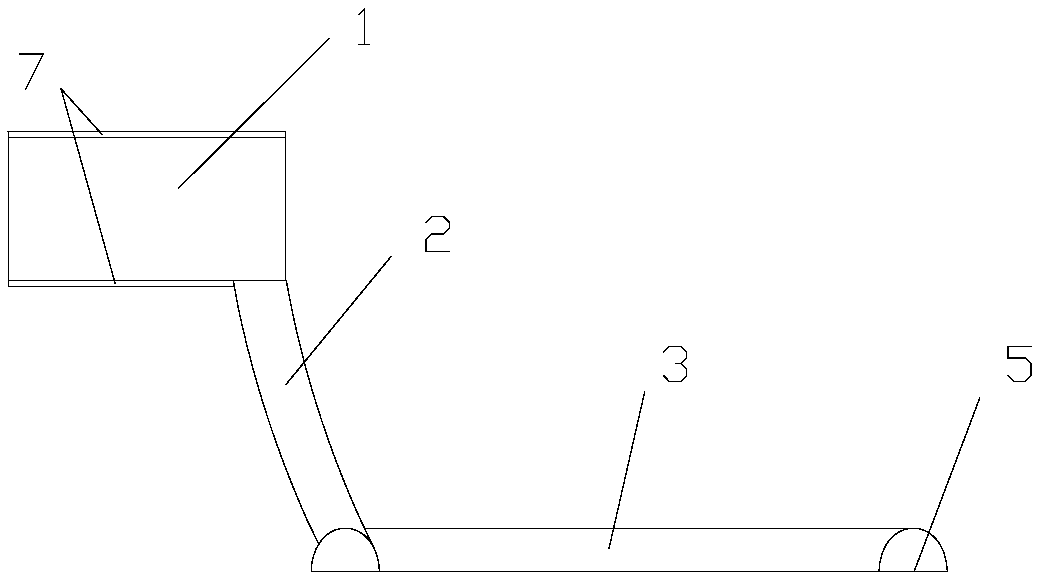
[0057] This embodiment is the same as embodiment 1, the difference is:

[0058] Such as Figure 4 As shown, the supporting part and the connecting part open a channel 8, and the connecting pipe 4 is led out through the channel 8.

Embodiment 3

[0060] This embodiment is the same as embodiment 2, the difference is:

[0061] Such as Figure 5 As shown, the angle between the two contact surfaces of the support member 1 is 10°.


PUM


Abstract

The present invention discloses an intraoral saliva suction support device. The intraoral saliva suction support device is composed of a support member, a connecting member and a saliva suction tube.The support member is a block structure, an opposite surface of the block structure is arranged to contact contact surfaces of dental crowns; the connecting member is the member that connects the support member to the saliva suction tube, besides, a connecting place of the connecting member and the support member has a set distance with a connecting place of the connecting member and the saliva suction tube, and one side of the connecting member is fixedly connected with a contact surface of the support member; the saliva suction tube is a U-shaped tube, a side wall of the U-shaped tube is fixedly connected with the other side of the connecting member, the U-shaped pipe communicates with a connecting tube for connecting a negative pressure generating device, an outer wall of one side of the U-shaped tube is used as a U-shaped working plane, the U-shaped working plane is parallel to a plane where the U-shaped tube is located, and a plurality of saliva suction holes are arranged in the U-shaped working plane; and the U-shaped working plane and the connecting member are located on both sides of the plane of the U-shaped tube, and the support member and the U-shaped tube are located onboth sides of a plane of the connecting member.

Description

technical field [0001] The disclosure belongs to the field of medical auxiliary equipment, and relates to an oral medical auxiliary equipment, in particular to a supporter for sucking saliva in the mouth. Background technique [0002] The statements herein merely provide background information related to the present invention and may not necessarily constitute prior art. [0003] The mouth is the beginning of the digestive tract. The front fissure communicates with the outside world, and the back passes through the pharynx to continue with the pharynx. There are teeth, tongue and other organs in the oral cavity. The front wall of the oral cavity is the lips, the side wall is the cheeks, the roof is the palate, and the floor of the mouth is the mucosa and muscles. The oral cavity is divided into the anterolateral oral vestibule and the posteromedial oral cavity by the upper and lower dental arches; when the upper and lower teeth occlude, the oral vestibule and the oral cav...

Claims


Application Information

Patent Timeline
Patent Type & Authority Applications(China)
IPC IPC(8): A61C17/06
Inventor 谈万业孙明霞刘超于璐彭化海宋晓彬李翠荣
Owner SHANDONG UNIV QILU HOSPITAL
Why Eureka
Try Eureka