Vein duct device capable of performing plugging
A technique for venous catheters and veins, which is applied in the direction of catheters, guide wires, guide needles, etc., and can solve the problem that the blocking wire is difficult to easily enter the lumen of venous catheters
- Summary
- Abstract
- Description
- Claims
- Application Information
AI Technical Summary
Problems solved by technology
Method used
Image

Examples
Embodiment 1
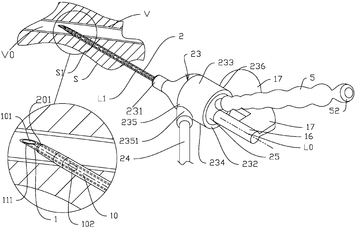
[0080] like Figure 1A , 1B , 1C, 1D, 1E, and 1F, Embodiment 1 of the present invention includes: a rigid needle tube 1 for puncturing the skin S and the vein wall V, a needle tube seat 16, an intravenous catheter 2, an intravenous catheter seat 23, and a sealing body 25. Plugging wire 3, plugging wire guiding passage 40, and isolation part 5; the inside of the needle tube 1 is hollow as the needle tube lumen 10, and the front part 11 of the needle tube is located in the vein catheter lumen 20, and the sharp needle tube front end 111 from the vein catheter front end The opening 201 is exposed; the inner cavity of the needle tube 10 is provided with an opening 101 at the front end of the needle tube, and the front part 11 of the needle tube is provided with a side opening 102 adjacent to the front end 111 of the needle tube; The inner cavity 230 of the intravenous catheter base is the needle tube passing part 14 inside the sealed body, the bottom of the needle tube 15 is fixed ...
Embodiment 2
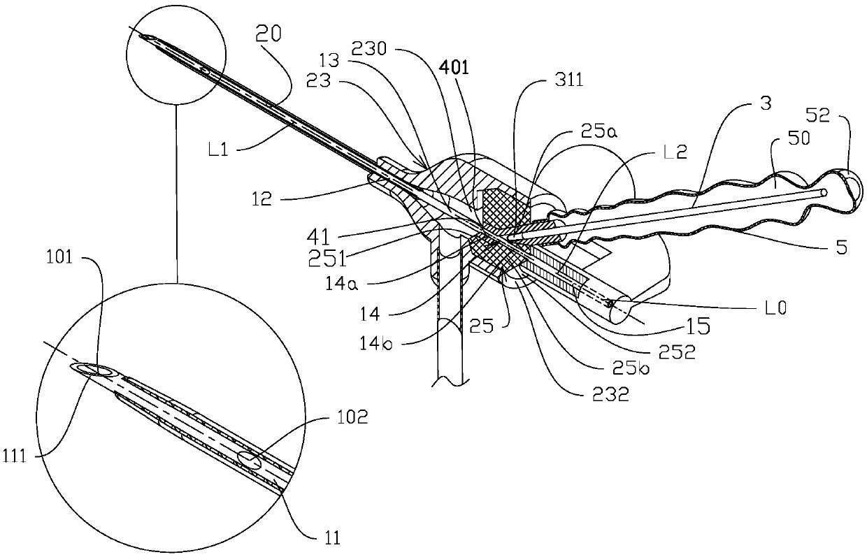
[0087] like Figure 2A , 2B , 2C, 2D, 2E, 2F, 2G, 2H, and 2I, the biggest difference from Embodiment 1 is that in the initial state, the central axis L2 of the straight tubular portion 41 of the guiding passage is not coaxial with the central axis L1 of the venous catheter but parallel relationship, Figure 2A It shows that the needle tube holder 16 is located below the isolation part 5, and the upper end surface 233 of the intravenous catheter holder 23 is provided with an arched window 2331, and a part of the hard part 25a of the sealing body is exposed in the arched window 2331, and the hard part 25a of the sealing body is connected with a handle 255, the handle 255 is connected to the hard part 25a of the sealing body through the neck 2551; Figure 2B The cross-section shows that the top end 311 of the front section of the occluding wire is located in the guiding passage 40 and is adjacent to the rear opening 402, the front opening 401 of the guiding passage faces the bo...
Embodiment 3
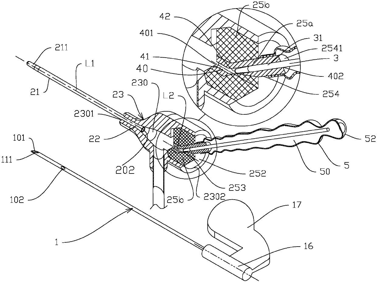
[0089] like Figure 3A , 3B , 3C, and 3D, the biggest difference from Embodiment 2 is that the central axis L2 of the straight tubular guide passage 40 on the sealing body 25 is collinear with the central axis L1 of the intravenous catheter through the externally isolated rotation method. The independent hollow passage member 4 is formed, and the collinearity is realized by means of translation rather than rotation for external isolation.
[0090] such as cutaway Figure 3A There is a tubular protruding part 2332 on the upper end surface 233 of the intravenous catheter seat, and the access part 4 is sleeved in the tubular protruding part 2332. The surface is sealingly connected with the outer surface of the tubular protrusion 2332, the passage member extension 43 is located in the inner cavity 50 of the isolation member, the passage member 4 can be driven by an external force acting on the extension 43 to displace relative to the tubular protrusion 2332, and the hollow part ...
PUM
 Abstract
Description
Claims
Application Information