Circular mechanical clamping part convenient to adjust

A mechanical clip and circular technology, applied in the mechanical field, can solve the problems of easy falling, damage to the workpiece, poor structural stability, etc., and achieve the effect of simple and convenient use, solving clamping problems, and strong practicability

Pending Publication Date: 2019-04-02
HUBEI ENG INST
View PDF0 Cites 3 Cited by
  • Summary
  • Abstract
  • Description
  • Claims
  • Application Information

AI Technical Summary

Problems solved by technology

[0003] On the basis of the existing technical conditions of mechanical clamping, there are still many deficiencies in the scope and convenience of semicircular clamping workpieces. Most semicircular clamping workpieces lack corres

Method used


Image

  • Circular mechanical clamping part convenient to adjust
  • Circular mechanical clamping part convenient to adjust
  • Circular mechanical clamping part convenient to adjust

Examples


Embodiment 1

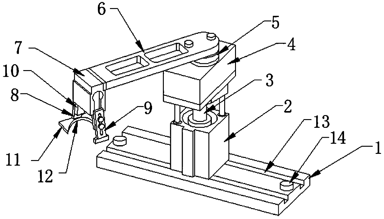
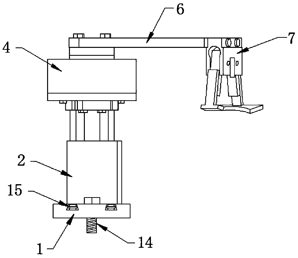
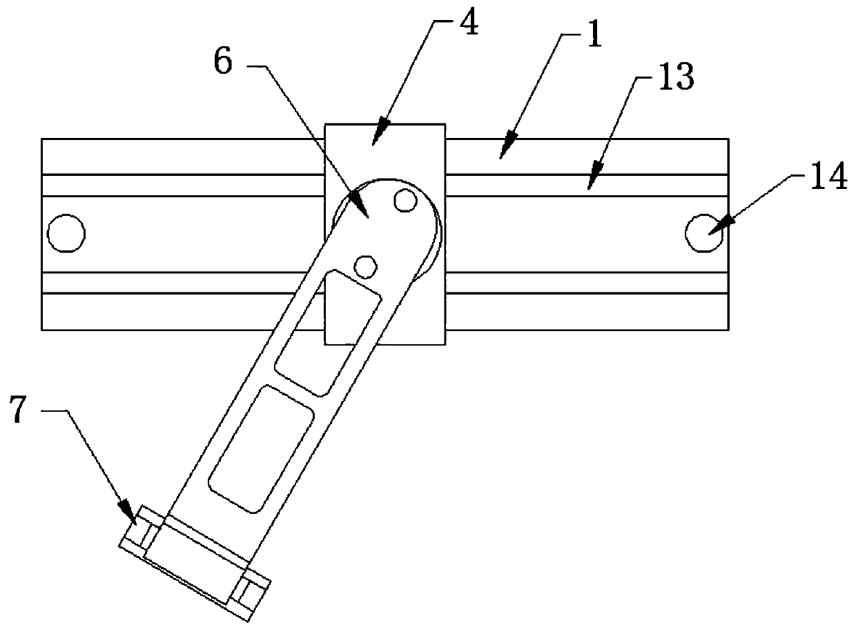
[0022] like Figure 1-3 As shown, the present invention provides a conveniently adjustable circular mechanical clamping member, comprising a sliding base 1, the surface of the sliding base 1 is provided with a moving slide rail 13, and a lifting drive seat 2 is installed on the moving slide rail 13, and the lifting The top of the drive seat 2 is provided with a lifting rod 3, the top of the lifting rod 3 is connected with a rotating base 4, the top of the rotating base 4 is provided with a rotating shaft 5, a rotating bracket 6 is installed on the rotating shaft 5, and one end of the rotating bracket 6 A working machine head 7 is provided, and the working machine head 7 is respectively provided with a first clamping frame 8 and a second clamping frame 9 .

[0023] Further, the bottom end of the first clamping frame 8 is provided with an ellipse clamping frame 11, and one side of the ellipse clamping frame 11 is provided with a notch 12, and the ellipse clamping frame 11 provid...


PUM


Abstract

The invention discloses a circular mechanical clamping part convenient to adjust. The circular mechanical clamping part convenient to adjust comprises a sliding base. The surface of the sliding base is provided with moving sliding rails. A lifting driving seat is mounted on the moving sliding rails. The top end of the lifting driving seat is provided with a lifting rod. The top end of the liftingrod is connected with a rotary base. The top end of the rotary base is provided with a rotary shaft. A rotary bracket is mounted on the rotary shaft. A working machine head is arranged at one end of the rotary bracket. The working machine head is provided with a first clamping rack and a second clamping rack. Through the circular mechanical clamping part convenient to adjust, the problems existingin clamping by a semicircular clamping part can be effectively solved. The clamping machine can do transverse movement through the moving sliding rails, conduct lifting adjustment through the liftingrods and conduct omni-directional adjustment through the rotary shaft and is easy and convenient to use and high in practicality.

Description

technical field [0001] The invention relates to the mechanical field, in particular to a conveniently adjustable circular mechanical clamping part. Background technique [0002] The robotic arm is the most widely used automatic mechanical device in the field of robotics. It can be seen in industrial manufacturing, medical treatment, entertainment services, military, semiconductor manufacturing, and space exploration. Although their shapes are different, they all have a common feature, that is, they can accept instructions and accurately locate a certain point in three-dimensional (or two-dimensional) space for operation. Joint robotic arm, Cartesian coordinate robotic arm, spherical coordinate robotic arm, polar coordinate robotic arm, cylindrical coordinate robotic arm, etc. The picture on the right shows a common six-degree-of-freedom robotic arm. He has X movement, Y movement, Z movement, X rotation, Y rotation, and Z rotation six degrees of freedom. [0003] On the ba...

Claims


Application Information

Patent Timeline
IPC IPC(8): B25J5/02B25J9/04B25J15/00
CPCB25J5/02B25J9/04B25J15/0033
Inventor 熊博昌袁慧明
Owner HUBEI ENG INST
Why Eureka
Try Eureka