Binding machine by means of annular rubber band

A strapping machine and rubber band technology, applied in the direction of bundling materials, etc., can solve the problems of low success rate, affecting the working stability of the machine, and uneven tightness

Inactive Publication Date: 2019-04-02
王秀来
View PDF4 Cites 4 Cited by
  • Summary
  • Abstract
  • Description
  • Claims
  • Application Information

AI Technical Summary

Problems solved by technology

The problem is: first, after the manipulator grabs the rubber band, the rubber band will sag, and the sagging of the rubber band will cause the inner diameter of the originally round rubber band to become elliptical, which is not conducive to the simultaneous insertion of four struts. The success rate is small, which seriously affects the working stability of the machine; the second is that the rubber band is easy to shake and shake during the process of being grasped and transferred by the manipulator, and it takes a long time to stabilize
The existing problem is that when the two pins of the horizontal stretching mechanism stretch the rubber band horizontally, the length of the circumference of the rubber band will be equally divided into upper and lower sections at the positions of the two pins, because the rubber band has a higher Elasticity, when the relative position of the two pins remains unchanged, when the upper rubber band (two pins) is tightened or pulled, only the upper rubber band can be tightened, while the lower rubber band Because the resistance of the two pins cannot be tightened, this phenomenon is generally called "not walking the rope".
When the two supporting rubber bands described in the comparative document 4 hold up the upper part of the rubber band upwards, although a trapezoid can be formed to be placed on the plastic bag, it can only tighten the upper part of the two pins. This makes the lower part of the rubber band looser and the upper part of the rubber band is too tight and easy to break
That is to say: the stretching and transposition of the rubber band in the comparative document 4 includes a horizontal stretching mechanism and a vertical stretching mechanism. The two rubber bands clamping your hands can only stretch the upper part of your rubber band, the lower part of the rubber band cannot be stretched tightly, but the upper part of the rubber band is easy to break if it is too tight, and it is precisely because of this way of supporting the elastic The degree is different, so it is difficult for this strapping machine to adapt to the market

Method used


Image

  • Binding machine by means of annular rubber band
  • Binding machine by means of annular rubber band
  • Binding machine by means of annular rubber band

Examples


Embodiment 2

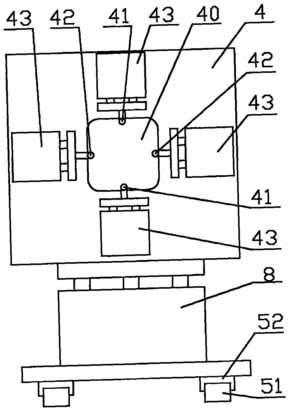
[0039] Embodiment two, such as Figure 8 , Figure 9 , Figure 10 Shown: the main differences between embodiment two and embodiment one are: first: the opening direction movement mechanism includes: frame 80, slide blocks are respectively installed on both sides of the bracket 4, so that the bracket 4 slides up and down and is arranged on the frame 80 Its two: the insertion motion mechanism is a kind of swing cylinder 53; its three: the delivery direction of the plastic bag delivery device is the left and right direction delivery, and the plastic bags folded into elongated strips are in the left and right horizontal state on the mechanical clamp 3, which is equivalent to The posture plane of the plastic bag 7 in the first embodiment is rotated 90 degrees counterclockwise.

[0040] Such as Figure 8 Shown: a frame 80 is set, a swing cylinder 53 is installed on the lower end of one side of the frame 80 and the frame 1, a guide rail 82 is installed up and down on both sides of...


PUM


Abstract

The invention discloses a binding machine by means of an annular rubber band. The annular rubber band is used for binding plastic bags which are folded into strips. The binding machine mainly comprises a machine frame, a vibration disc device and a plastic bag conveying device; and the binding machine is characterized in that a U-shaped notch is further formed in the vibration disk device, and a rubber band stretching device is further arranged at the position, corresponding to the U-shaped notch; the rubber band stretching device mainly comprises a support, an opening-direction supporting rod, two side supporting rods, an opening-direction movement mechanism and an inserting movement mechanism; and the inserting movement mechanism firstly drives the supporting rod to be inserted into theannular rubber band at the U-shaped notch, the opening-direction movement mechanism moves the annular rubber band out of the vibration disc device and then stretches the annular rubber band to carry out the binding function. According to the binding machine, a mechanical arm rubber band transferring device in the prior art is omitted, mechanisms such as a rib removing plate and a blocking ring areomitted, so that the working links are reduced, the work is stable, the structure is simple and compact, and the yield of the binding is high.

Description

technical field [0001] The invention relates to a ring-shaped rubber band binding machine, in particular to a binding machine which adopts a ring-shaped rubber band to bind plastic bags. Background technique [0002] The plastic bags automatically produced by the bag making machine, in order to facilitate storage, sales and use, these plastics need to be folded into long strips, and then tied with a ring rubber band in the middle of the folded long strips of plastic bags before they can enter the market . [0003] Authorized notification number CN208070086U discloses an automatic strapping machine (hereinafter referred to as reference document 1), which mainly includes: a main material feeding mechanism, an auxiliary material feeding mechanism, and a strapping mechanism. Its binding mechanism includes a spreader and a manipulator. Application publication number CN108773518A discloses an "automatic binding device for plastic bag making machine" (hereinafter referred to as r...

Claims


Application Information

Patent Timeline
Patent Type & Authority Applications(China)
IPC IPC(8): B65B13/02
Inventor 王秀来
Owner 王秀来
Why Eureka
Try Eureka