Thermoacoustic refrigerator
A technology of thermoacoustic refrigerator and cold head, which is applied in refrigerators, refrigeration and liquefaction, lighting and heating equipment, etc., and can solve problems such as difficulty in using low-temperature refrigerators and limited refrigeration effect of regenerator 12, and achieve reduction Effect of mixing loss and high cooling effect
- Summary
- Abstract
- Description
- Claims
- Application Information
AI Technical Summary
Problems solved by technology
Method used
Image

Examples
Embodiment 1
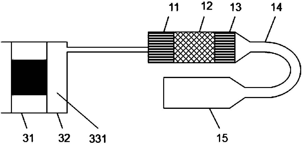
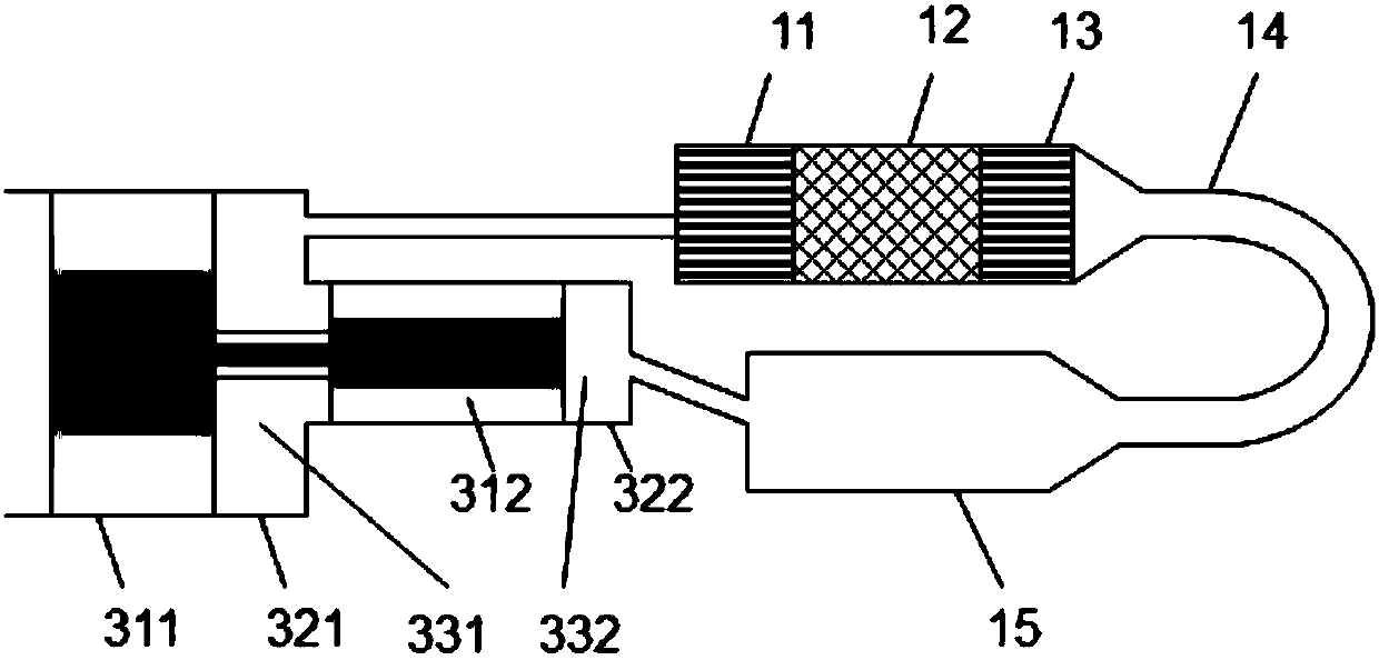
[0028] This embodiment provides a thermoacoustic refrigerator, such as figure 2 As shown, it includes a compressor 3 and a cold head 1. The cold head 1 is composed of a radiator 11, a regenerator 12, a cold heat exchanger 13, an inertia tube 14 and an air reservoir 15. The compressor 3 adopts a stepped piston structure to form a compression The cavity 331 and the expansion cavity 332 are connected, the compression cavity 331 is connected to the radiator 11, and the expansion cavity 332 is connected to the air reservoir 15.
[0029] Among them, the piston of the compressor 3 is divided into steps, consisting of a first-stage piston 311 and a second-stage piston 312, and the cylinder of the compressor 3 is also divided into a stepped type, consisting of a first-stage cylinder 321 and a second-stage cylinder 322, thus A compression cavity 331 and an expansion cavity 332 are formed.
[0030] One end of the second-stage piston 312 and the second-stage cylinder 322 is at room temperatur...
Embodiment 2
[0038] In order to obtain a lower temperature, the refrigerator is made into a two-stage refrigerator in this embodiment.
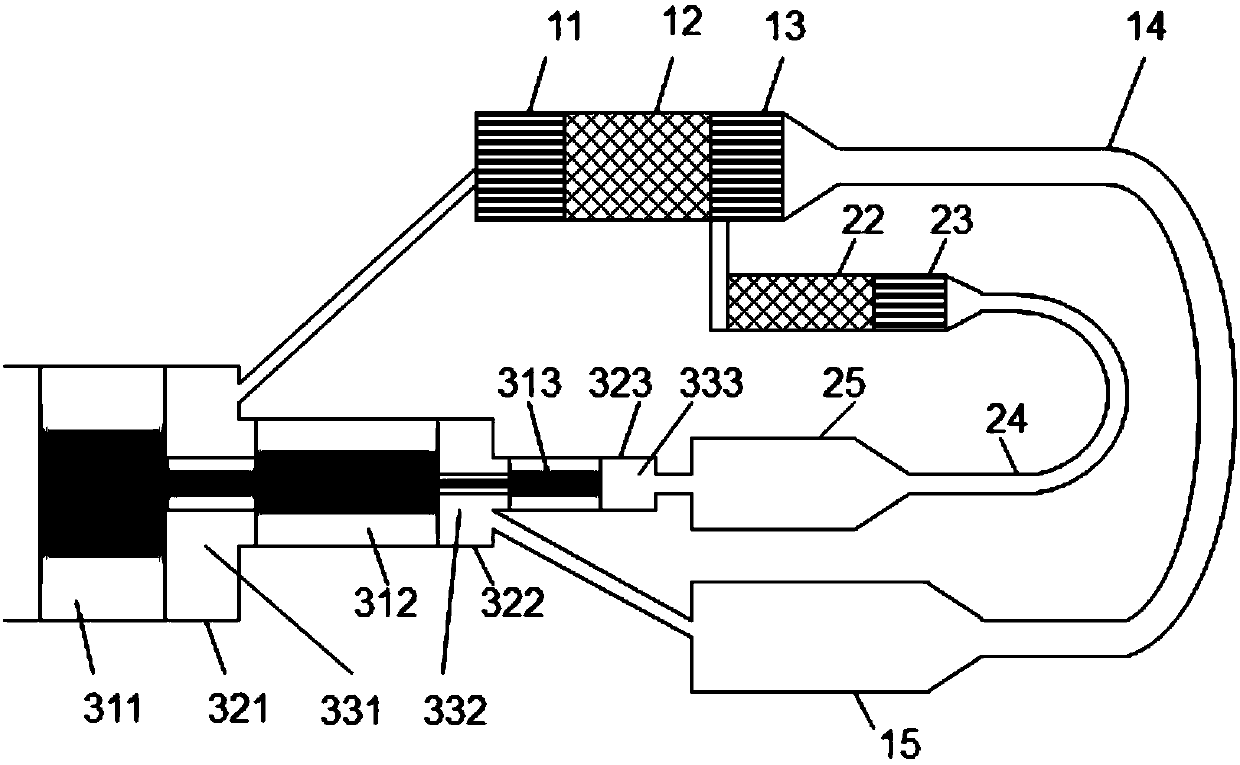
[0039] In this embodiment, the thermoacoustic refrigerator is such as image 3 As shown, it includes a compressor and a cold head. Among them, the compressor is made into three stages, that is, the piston is divided into steps, consisting of a first-stage piston 311, a second-stage piston 312, and a third-stage piston 313. The cylinder of the compressor is also Divided into three stages, it is composed of a first-stage cylinder 321, a second-stage cylinder 322 and a third-stage cylinder 323, so that a compression chamber 331 is formed between the first-stage piston 311 and the first-stage cylinder 321, and the second-stage piston 312 A first expansion chamber 332 is formed between the second-stage cylinder 322 and a second expansion chamber 333 is formed between the third-stage piston 313 and the third-stage cylinder 323.
[0040] The cold head consists of a r...
Embodiment 3
[0045] In order to obtain a lower temperature, the refrigerator is made into a two-stage refrigerator in this embodiment.
[0046] In this embodiment, the thermoacoustic refrigerator is such as Figure 4 As shown, it includes a compressor and a cold head. Among them, the compressor is made into three stages, that is, the piston is divided into steps, consisting of a first-stage piston 311, a second-stage piston 312, and a third-stage piston 313. The cylinder of the compressor is also Divided into three stages, it is composed of a first-stage cylinder 321, a second-stage cylinder 322 and a third-stage cylinder 323, so that a compression chamber 331 is formed between the first-stage piston 311 and the first-stage cylinder 321, and the second-stage piston 312 A first expansion chamber 332 is formed between the second-stage cylinder 322 and a second expansion chamber 333 is formed between the third-stage piston 313 and the third-stage cylinder 323.
[0047] The cold head consists of a ...
PUM
 Abstract
Description
Claims
Application Information
 - R&D
- Intellectual Property
- Life Sciences
- Materials
- Tech Scout
- Unparalleled Data Quality
- Higher Quality Content
- 60% Fewer Hallucinations
Browse by: Latest US Patents, China's latest patents, Technical Efficacy Thesaurus, Application Domain, Technology Topic, Popular Technical Reports.
© 2025 PatSnap. All rights reserved.Legal|Privacy policy|Modern Slavery Act Transparency Statement|Sitemap|About US| Contact US: help@patsnap.com