A method for converting blade non-contact vibration stress measurement value

A vibration stress, non-contact technology used in vibration testing, measuring devices, measurement of elastic deformation forces by measuring gauges, etc.

Active Publication Date: 2021-02-19
AECC SICHUAN GAS TURBINE RES INST
View PDF9 Cites 0 Cited by
  • Summary
  • Abstract
  • Description
  • Claims
  • Application Information

AI Technical Summary

Problems solved by technology

The vibration stress conversion method involved in the present invention is based on the principle of non-contact measurement, combined with the theoretical analysis results, mainly for processing the test data of non-contact measurement of engine blades, and solves how to accurately convert the vibration displacement of the blade tip obtained by non-contact measurement into blade tip vibration displacement. Body Vibration Stress Distribution Problem

Method used


Image

  • A method for converting blade non-contact vibration stress measurement value
  • A method for converting blade non-contact vibration stress measurement value
  • A method for converting blade non-contact vibration stress measurement value

Examples


Embodiment Construction

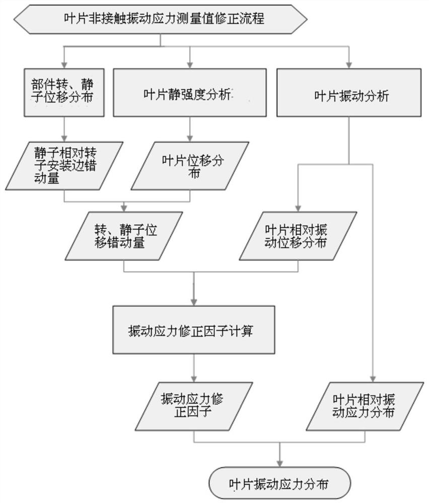
[0030] The specific process of the correction of the blade non-contact vibration stress measurement value is as follows: figure 1 shown.

[0031] It can be seen from the above figure that the correction of the non-contact vibration stress measurement value of the blade needs to be corrected in terms of the axial misalignment of the rotor stator and the vibration deformation of the blade. Here, taking the first-stage rotor blade of a certain engine fan component as an example, the correction method Make an introduction:

[0032] 1) Correction for axial misalignment of rotor and stator

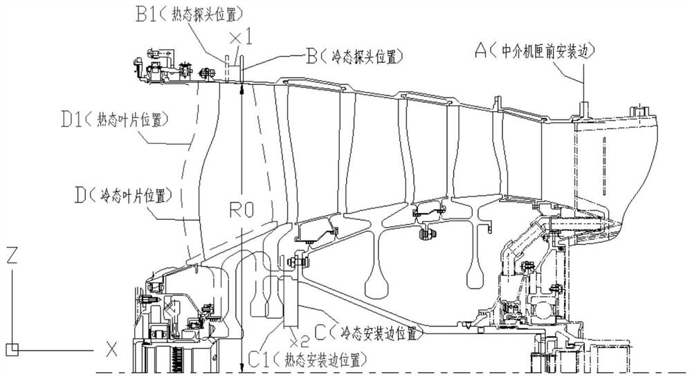
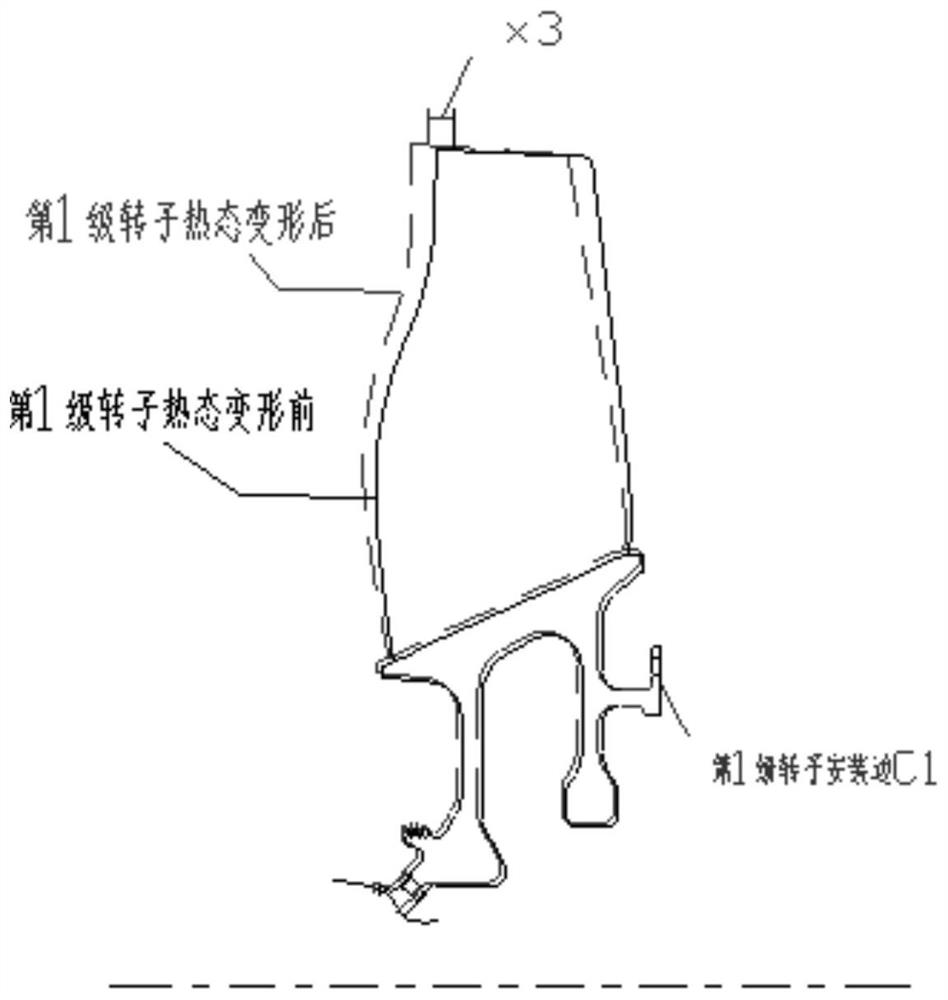
[0033] The engine coordinate system is defined as a right-handed Cartesian coordinate system: X is along the axial direction of the engine, positive along the airflow direction, Z is vertical along the engine, positive vertically upward, and the Y axis is determined by the right-hand rule. Figure 2a-2b It is a schematic diagram of thermal axial deformation of fan rotor and stator components o...


PUM


Abstract

Disclosed is a non-contact vibration stress measurement value conversion method for blades, including: 1) Correction of the axial misalignment of the rotor and the stator: determining the axial misalignment X0 of the rotor and the stator, X0=X1-(X2+X3), where : X1 is the axial displacement of the measuring sensor relative to the reference position; X2 is the axial displacement of the mounting edge of the rotor blade relative to the reference position; X3 is the axial displacement of the tip of the rotor blade relative to the mounting edge of the rotor blade ; 2) Correction of blade vibration deformation: Utilize the axial misalignment X0 to determine the measured point of the blade tip of the rotor blade, combine the measured vibration displacement of the blade tip and the relative vibration displacement distribution obtained through the finite element method to obtain the scaling factor K, by The relative vibration stress distribution determined by the finite element method is divided by the relative vibration displacement distribution scaling factor K to obtain the real vibration stress distribution σ i .

Description

technical field [0001] The invention relates to a method for converting vibration stress measurement values, in particular to a non-contact vibration stress measurement value conversion method for aeroengine blades. Background technique [0002] The invention starts from the basic principle of the non-contact measurement of the blade tip timing method, and clarifies the conversion method of the non-contact measurement of the vibration displacement of the blade tip to the vibration stress of the blade body. By combining the experimental data and theoretical calculation results, the process and method of converting the non-contact measurement vibration displacement of the blade into the vibration stress distribution of the blade are clarified. The non-contact vibration stress measurement value conversion method adopted in the present invention has been applied to the dynamic stress measurement of the QC engine fan rotor blade. And in order to verify the reliability of the met...

Claims


Application Information

Patent Timeline
Patent Type & Authority Patents(China)
IPC IPC(8): G01L1/04G01M7/02
CPCG01L1/04G01M7/02
Inventor 何凌川刘亮王梅黎方娟
Owner AECC SICHUAN GAS TURBINE RES INST
Why Eureka
Try Eureka