Method for extracting radiation defect of linear circuit

A linear circuit and extraction method technology, applied in the direction of measuring electricity, measuring electrical variables, measuring devices, etc., can solve problems such as inability to separate discrete devices, achieve enrichment of low dose rate enhancement effects, improve speed and accuracy, and achieve good research results Effect

Active Publication Date: 2019-04-02
HARBIN INST OF TECH +2
View PDF6 Cites 3 Cited by
  • Summary
  • Abstract
  • Description
  • Claims
  • Application Information

AI Technical Summary

Benefits of technology

This patented technology helps identify small electrical faults caused during use or operation of electronic components such as semiconductor chips (chips). By doing this it allows scientists to study these systems more accurately without having to separate them from their surrounding environment. It also simplifies the testing procedures needed beforehand, making it faster than traditional methods like X-ray inspections. Overall, its technical benefits include improved accuracy and efficiency in detecting smaller electrically induced errors in electronic componentry used in various applications including medical imagery equipment, defense electronics, space exploration tools, etc., which are becoming increasingly important due to advancements made over time towards higher levels of safety regulations worldwide.

Problems solved by technology

The technical problem addressed in this patents relates to evaluating the impact of low dosage rates during exposure to solar particles or other sources like X rays while maintaining their functionality over long periods of use without being affected negatively due to environmental factors like gamma ray burst events.

Method used


Image

  • Method for extracting radiation defect of linear circuit
  • Method for extracting radiation defect of linear circuit
  • Method for extracting radiation defect of linear circuit

Examples


Embodiment 1

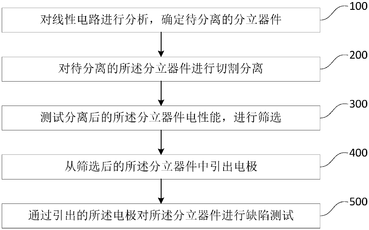
[0045] Such as figure 1 As shown, it is; Wherein, the linear circuit radiation defect extraction method includes:

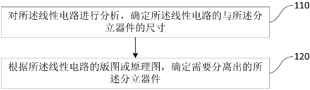
[0046] Step 100, analyzing the linear circuit to determine the discrete device to be separated;

[0047] Analyze the linear circuit. Under the influence of external radiation, the overall performance of the linear circuit itself degrades, and the circuit parameters change greatly. Through the analysis of the linear circuit, the purpose is to preliminarily determine that the large change in parameters may be due to the linear circuit. Which discrete devices are caused by these discrete devices, and these discrete devices that may affect large changes in parameters are discrete devices that need to be independently extracted for defects, that is, discrete devices to be separated.

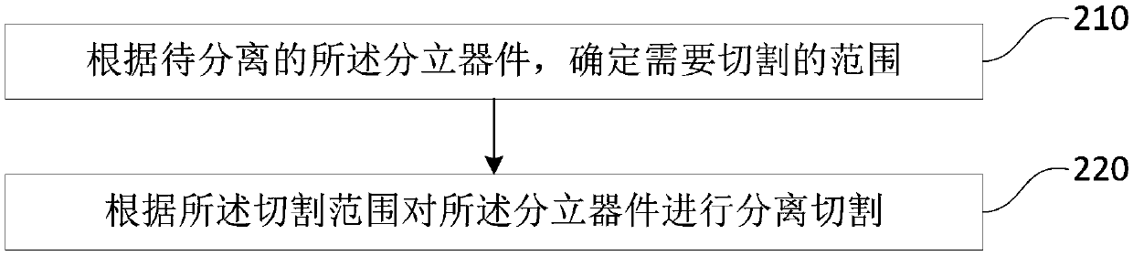
[0048] Step 200, cutting and separating the discrete device to be separated;

[0049] By cutting, the discrete devices to be separated are separated, so that the separated discrete dev...

Embodiment 2

[0092] The difference between this embodiment and the above-mentioned linear circuit radiation defect extraction method is that the linear circuit 7J139 is taken as an example in this embodiment to describe the linear circuit radiation defect extraction method.

[0093] The defect extraction process using linear circuits is as follows:

[0094] (1) Clarify the size of the circuit die (discrete device size), the die size of 7J139 is: 1.03mm×1.00mm×0.32mm, the layout of the die is as follows Figure 6 shown.

[0095] (2) Label the internal units of the die and determine the schematic diagram. The die layout after the label is as follows Figure 7 As shown (wherein, the labels in the figure are for distinguishing during the radiation defect extraction process, and are not the reference signs of this application), for the 7J139 circuit, there are 14 lead-out terminals, 8 vertical PNP tubes, and horizontal PNP tubes. There are 17 tubes, 8 diodes formed by horizontal PNP tubes, 1...


PUM


Abstract

The invention provides a method for extracting a radiation defect of a linear circuit. The method comprises: step 100, analyzing the linear circuit to determine discrete devices to be separated; step200, cutting and separating the discrete devices to be separated; step 300, testing the electrical properties of the separated discrete devices for screening; step 400, extracting an electrode from the screened discrete devices; step 500, testing the defect on the discrete devices by the extracted electrode. According to the method for extracting the radiation defect of the linear circuit, the discrete devices in the linear circuit are separated for extracting the electrode by the cutting and screening the discrete devices, so that the defect test can be independently performed on the discretedevices in the linear circuit, so that the research of the existing enhancement effect with a low dose rate is enriched, and a better research effect is achieved.

Description


Claims


Application Information

Patent Timeline
Owner HARBIN INST OF TECH
Why Eureka
Try Eureka