
Multifunctional photoelectric composite cable cross connecting cabinet

An optical cable junction box, optoelectronic composite cable technology, applied in the coupling of optical waveguides, optical guides, optics, etc., can solve the problems of maintenance and operation management difficulties, and achieve the effect of facilitating attendance, ensuring equipment cooling, and ensuring internal temperature balance.

Inactive Publication Date: 2019-04-02
江苏天源太阳能发电有限公司
View PDF0 Cites 2 Cited by
  • Summary
  • Abstract
  • Description
  • Claims
  • Application Information

AI Technical Summary

Problems solved by technology

[0002] With the rapid development of FTTH construction, the continuous demand of enterprises and users for optical fiber access has greatly increased the number of service access points, and the optical transmission box equipment at the convergence point is widely distributed in various nodes in cities and suburbs, and it is necessary for operators to monitor and maintain in the later stage Difficulties and challenges brought to operation and management: maintenance of optical fiber lines, convenient fault finding, inspection and attendance records of inspection and maintenance personnel, alarm protection of equipment

Method used


Image

  • Multifunctional photoelectric composite cable cross connecting cabinet
  • Multifunctional photoelectric composite cable cross connecting cabinet
  • Multifunctional photoelectric composite cable cross connecting cabinet

Examples


Embodiment Construction

[0024] The present invention will be further described below in conjunction with the embodiments and the accompanying drawings.

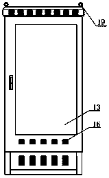
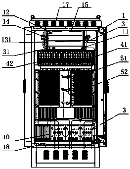
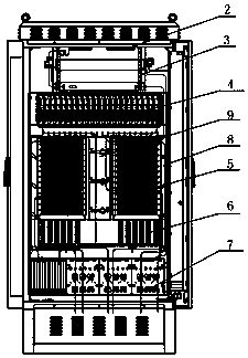
[0025] Such as Figure 1-2 As shown, a multifunctional photoelectric composite optical cable transfer box includes a box body 1, and the box body 1 is provided with an exhaust area 2 from top to bottom, an equipment unit installation area 3, and a smart box-type optical division installation area 4 , the intelligent fusion module installation area 5, the intelligent fusion module installation area 5 is provided with a trunk fusion integration tray 51 and a wiring fusion integration tray 52; a pigtail parking area 6, and a photoelectric composite cable stripping area 7 The upper cable channel 8 is located on one side of the box body 1; the fiber channel 9 is located in the middle of the box body 1; the direct melting unit 10 is located on the left side of the photoelectric composite cable stripping area 7; A box-type optical distribution installatio...


PUM


Abstract

The invention relates to the field of fiber communication, and relates to a multifunctional photoelectric composite cable cross connecting cabinet. The multifunctional photoelectric composite cable cross connecting cabinet comprises a box body, wherein from top to bottom, the box body is internally provided with an air exhaust area, an equipment unit installation area, an intelligent box type light split installation area, an intelligent melt distribution module installation area, a tail fiber parking area, and a photoelectric composite cable stripping area in sequence, a cable feeding passageis arranged at one side of the interior of the box body, and a fiber through passage is arranged in the middle of the box body. Compared with the prior art, the multifunctional photoelectric composite cable cross connecting cabinet has clear function areas, supports installation of an intelligent box type light splitter and an intelligent melt distribution integrated support tray, and can outputa wiring user end of high core number while realizing non jumper connection and low loss transmission so as to make the equipment extended intelligently; good air exhaust system balances internal temperature; an advertisement screen is configured through a box door, a power part of the advertisement screen is connected with inward distribution equipment, so that additional economic value is created for operators by advertising.

Description

technical field [0001] The invention relates to the field of optical fiber communication, and is a multifunctional photoelectric composite optical cable transfer box. Background technique [0002] With the rapid development of FTTH construction, the continuous demand of enterprises and users for optical fiber access has greatly increased the number of service access points, and the optical transmission box equipment at the convergence point is widely distributed in various nodes in cities and suburbs, and it is necessary for operators to monitor and maintain in the later stage Difficulties and challenges brought to operation and management: maintenance of optical fiber lines, convenient fault finding, inspection and attendance records of inspection and maintenance personnel, and alarm protection of equipment. [0003] The large distribution of photoelectric composite optical cable transfer boxes in urban streets and some main roads in the suburbs is a kind of platform resour...

Claims


Application Information

Patent Timeline
IPC IPC(8): G02B6/44G02B6/255G09F23/00
CPCG02B6/4446G02B6/255G02B6/4448G09F23/00
Inventor 刘建平
Owner 江苏天源太阳能发电有限公司
Learn More