Teaching device based on emission device in electromagnetic coupling transmission, and experiment method

A transmitting device and electromagnetic coupling technology, which is applied in the field of teaching devices based on transmitting devices in electromagnetic coupling transmission, can solve the problems of small coil rotation angle intervals, difficulties in adding and subtracting coils, and bulky training devices, so as to achieve savings in replacing coils, Precisely adjust the effect of automatic rotation angle

Pending Publication Date: 2019-04-02
TIANJIN SINO GERMAN VOCATIONAL TECHNICAL COLLEGE
View PDF6 Cites 0 Cited by
  • Summary
  • Abstract
  • Description
  • Claims
  • Application Information

AI Technical Summary

Problems solved by technology

[0003] The training device disclosed in patent CN106940957A (201710337841.5) is bulky and has a single function. It can only do a single targeted experiment. It is difficult to add and subtract coils during the comparison experiment, and the experimental operation steps are extremely cumbersome
The coil rotation angle cannot be adjusted automatically, and manual adjustment greatly reduces the reliability of the experimental data. Since the track runs through the coil, the coil rotation angle range is small, which greatly reduces the operability of the device. At the same time, the patent discloses that the coil and the track are fixed As a result, the distance between the coils cannot be changed, and the relationship between the distance and the transmission efficiency cannot be studied, thus reducing the application range of this experimental device

Method used


Image

  • Teaching device based on emission device in electromagnetic coupling transmission, and experiment method
  • Teaching device based on emission device in electromagnetic coupling transmission, and experiment method
  • Teaching device based on emission device in electromagnetic coupling transmission, and experiment method

Examples


Embodiment Construction

[0028] The present invention will be described in detail below in conjunction with the accompanying drawings and embodiments.

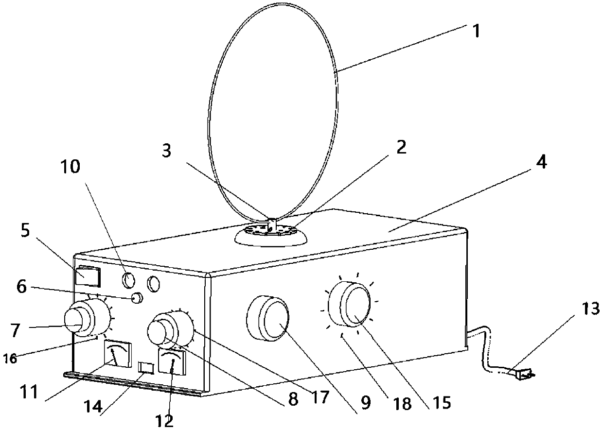
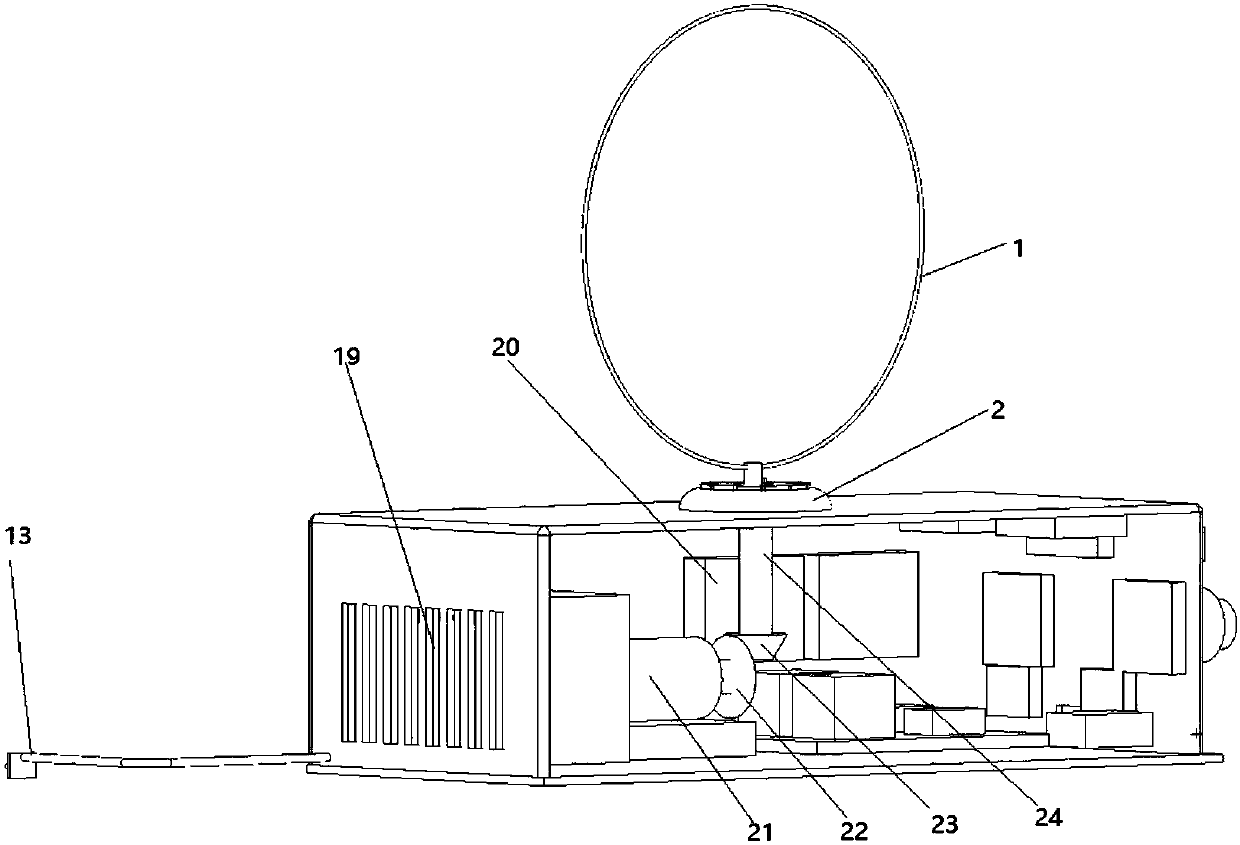
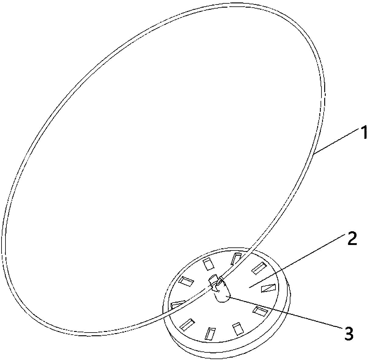
[0029] Such as Figure 1-4 As shown, a teaching device based on a transmitting device in electromagnetic coupling transmission includes a transmitting coil 1, a rotating platform 2 for fixing the transmitting coil, a housing 4 and is arranged in the housing for driving the A rotating mechanism for rotating the rotating platform; the rotating mechanism includes a motor knob 15 arranged on the side wall of the housing, a motor drive module 20 connected to the motor knob, driven by the motor drive module The stepper motor 21, the bevel gear connected with the stepper motor and the connecting shaft 24 connected with the bevel gear; the stepper motor 18 is a 12v stepper motor of 35BYJ412B, and the stepper motor The drive module adopts the ULN2003 drive module, and the bevel gear is selected from a 40-tooth 5-mode bevel gear and a 15-tooth 5-mode bevel gea...


PUM


Abstract

The invention belongs to the technical field of teaching device, and more specifically relates to a teaching device based on an emission device in electromagnetic coupling transmission, and an experiment method. The teaching device comprises a transmitting coil, a rotary platform used for fixing the transmitting coil, a housing, and a rotary mechanism which is arranged in the housing and is used for driving the rotary platform to rotate; the rotary mechanism comprises a motor rotary knob arranged on the side wall of the housing, a motor driving module connected with the motor rotary knob, a stepping motor driven by the motor driving module, a bevel gear connected with the stepping motor, and a connecting shaft connected with the bevel gear; the other end of the connecting shaft is designedto penetrate through the housing, is connected with the rotary platform, and is used for driving the rotary platform to rotate. The beneficial effects are that: device modularization is adopted, direct inset type is adopted by the coil, continuous inserting and extracting can be realized, it is convenient for increasing and reducing coils and replacing coils in experiment process, and large amount of time is saved. The coil rotating angle is controlled by stepping motor transmission, and gear engagement is capable of realizing accurate adjusting of automatic rotation angle of coils.

Description

technical field [0001] The invention relates to the technical field of teaching devices, in particular to a teaching device and an experimental method based on a transmitting device in electromagnetic coupling transmission. Background technique [0002] In November 2006, MarinSoljacic, an assistant professor in the MIT Department of Physics, proposed a new theory that can utilize electromagnetic energy through wireless energy transfer technology. Two coils of copper wire are used as resonators, one coil is connected to the power supply and acts as a transmitter; the other is connected to a desk lamp and acts as a receiver. As a result, they successfully lit a 60-watt electric lamp 2.13 meters away from the transmitter. Among them, electromagnetic induction wireless power supply technology is a new field that domestic and foreign academic circles and industrial circles have begun to explore, and it belongs to the frontier topic in the field of electric energy transmission in...

Claims


Application Information

Patent Timeline
Patent Type & Authority Applications(China)
IPC IPC(8): G09B23/18
CPCG09B23/181
Inventor 刘艺柱赵翠霖王旭东王晨岳峰陈莎莎
Owner TIANJIN SINO GERMAN VOCATIONAL TECHNICAL COLLEGE
Why Eureka
Try Eureka