Direct-current relay for resisting short-circuit current

A DC relay and anti-short circuit technology, applied in the direction of electromagnetic relays, relays, electromagnetic relay details, etc., can solve the problems that the contact pressure is not enough to resist the electric repulsion of the moving spring, cannot provide sufficient suction, and the DC relay is small in size, etc., to achieve The magnetic circuit is not easy to be saturated, the cost is low, and the effect of high magnetic efficiency

Pending Publication Date: 2019-04-02
XIAMEN HONGFA ELECTRIC POWER CONTROLS
View PDF0 Cites 7 Cited by
  • Summary
  • Abstract
  • Description
  • Claims
  • Application Information

AI Technical Summary

Problems solved by technology

The short-circuit resistance requirement of typical input currently required by the market is 8000A, and it will not burn or explode within 5ms; while the DC relays of the prior art cannot provide sufficient suction force while maintaining the characteristics of small size, that is, the contact pressure is not enough to resist the force of the moving spring. electric repulsion, so it is difficult to meet market requirements

Method used


Image

  • Direct-current relay for resisting short-circuit current
  • Direct-current relay for resisting short-circuit current
  • Direct-current relay for resisting short-circuit current

Examples


Embodiment 1

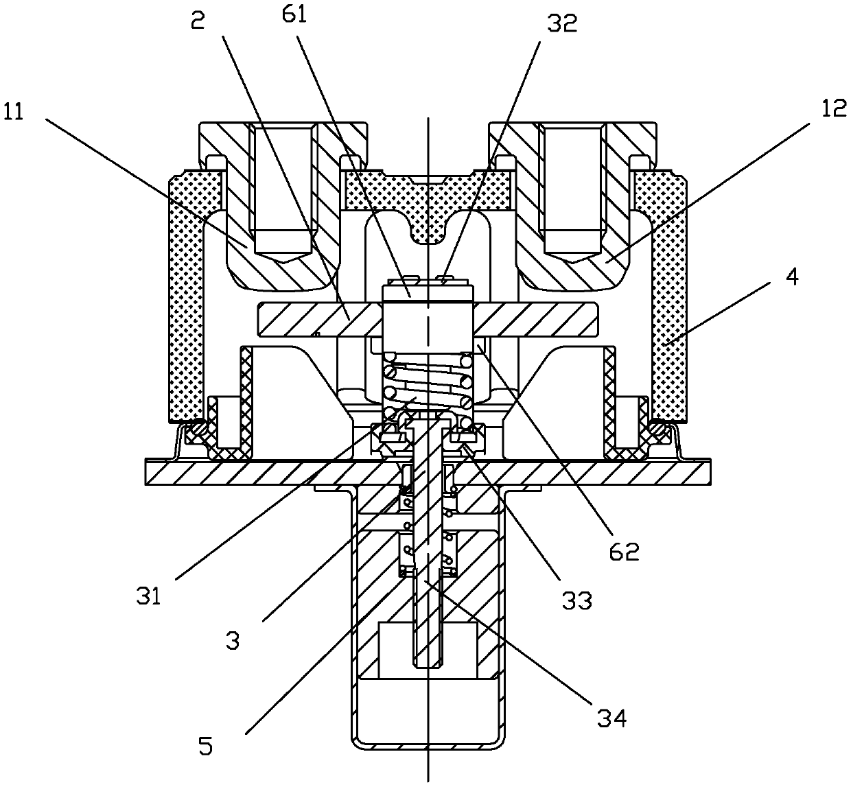
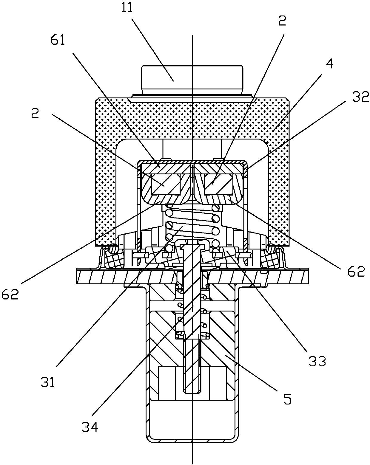
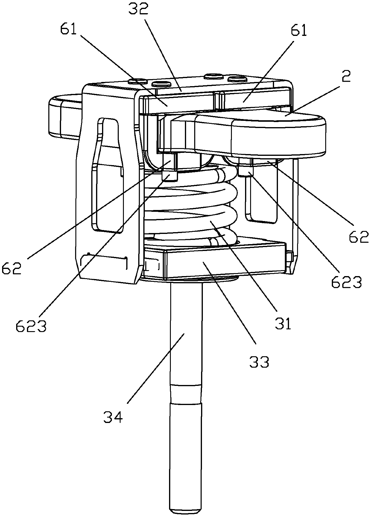
[0044] see Figure 1 to Figure 11 As shown, a kind of short-circuit current DC relay of the present invention includes two static contact terminals 11, 12 for current inflow and current outflow respectively, a straight-type movable reed 2 and a Drive the moving reed 2 to move to realize the moving contact at the two ends of the moving reed and the static contact at the bottom of the static contact lead-out end to contact or disconnect the push rod part 3; On the casing 4, a part of the moving reed 2 and the push rod part 3 is accommodated in the casing 4, and the push rod part 3 is also connected with the moving iron core 5 in the magnetic circuit structure, and under the action of the magnetic circuit, the push rod Part 3 drives the movable reed 2 to move upwards, so that the movable contacts at both ends of the movable reed 2 are respectively in contact with the static contacts at the bottom ends of the two static contact lead-out ends 11 and 12, so as to realize the connect...

Embodiment 2

[0064] see Figure 12 to Figure 13 As shown, a DC relay against short-circuit current of the present invention differs from Embodiment 1 in that the upper magnetic conductor 61 is an upper yoke, and the upper yoke is fixed on the On the housing of the lead-out end, like this, when the movable contact of movable reed 2 and the static contact of static contact lead-out 11,12 did not contact and cooperate (that is, when the contacts were disconnected), the upper magnetic conductor 61 (upper There is a preset gap between the lower magnetic conductor 62 (lower armature), and when the movable contact of the movable reed 2 is in contact with the static contacts of the static contact lead-out ends 11 and 12, the upper The magnetic conductor 61 is in contact with the lower magnetic conductor 62 , that is, there is basically no gap between the upper magnetic conductor 61 and the lower magnetic conductor 62 .

Embodiment 3

[0066] see Figure 14 to Figure 16 As shown, a DC relay with short-circuit current resistance of the present invention is different from Embodiment 1 in that there are three magnetic conduction circuits, and the moving reed 2 is provided with two through holes 22, and three U-shaped The lower magnetic conductors 62 are arranged sequentially along the width of the moving reed 2, wherein the two side walls 621, 622 of a U-shaped lower magnetic conductor 62 in the middle pass through the two through holes 22 of the movable reed respectively, and the two through holes 22 on both sides Each side wall 621 of the U-shaped lower magnetic conductor 62 is attached to the corresponding side of the width of the moving reed respectively, and each other side wall 622 of the two U-shaped lower magnetic conductors 62 on both sides passes through the two sides of the movable reed respectively. There is a through hole 22, and there is a gap between the side walls 622 of the two U-shaped bottom ...


PUM


Abstract

The invention discloses a direct-current relay for resisting a short-circuit current. The direct-current relay for resisting the short-circuit current comprises two static contact leading-out ends, amovable spring piece and a pushing rod part; an upper magnetizer is arranged above a preset position of the movable spring piece, and a lower magnetizer capable of moving along with the movable springpiece is arranged below the preset position of the movable spring piece; and at least one through hole is formed in the movable spring piece at the preset position, so that the upper magnetizer and the lower magnetizer can be close to or in mutual contact with each other through the through hole, and at least two independent magnetic conductive circuits are formed on the width of the movable spring piece by the upper magnetizer and the lower magnetizer. According to the direct-current relay, the magnetic pole surfaces are added at the positions of the corresponding through holes of the respective magnetic conductive circuits, so that when the moving spring piece suffers from a fault large current, suction force in the pressure direction of the contact is generated, and the electric repulsive force generated by the fault current between the movable spring piece and the static contact leading-out ends is resisted, and therefore the relay has the characteristics of high magnetic efficiency and difficulty in magnetic circuit saturation.

Description

technical field [0001] The invention relates to the technical field of relays, in particular to a DC relay against short-circuit current. Background technique [0002] A DC relay in the prior art adopts a direct-acting magnetic circuit structure, and two static contact terminals (that is, two load terminal terminals) are respectively installed on the housing, and the bottom ends of the two static contact terminal terminals are arranged There are static contacts, the current of one of the static contact terminals flows in, and the current of the other static contact terminal flows out. A moving spring and a push rod part are installed in the housing. The moving spring adopts a straight-type moving reed (also known as Bridge-type moving reed), the moving reed is installed in the push rod part through the spring, the push rod part is connected with the direct-acting magnetic circuit, under the action of the direct-acting magnetic circuit, the pushing rod part drives the moving ...

Claims


Application Information

Patent Timeline
Patent Type & Authority Applications(China)
IPC IPC(8): H01H50/64H01H50/16H01H1/54
CPCH01H50/64H01H1/54H01H50/16
Inventor 钟叔明代文广傅大鹏王萌
Owner XIAMEN HONGFA ELECTRIC POWER CONTROLS
Why Eureka
Try Eureka