

Flux increase type built-in U type adjustable magnetic flux motor
A magnetic flux motor, U-shaped technology, applied in the direction of magnetic circuit shape/style/structure, magnetic circuit, synchronous machine, etc., can solve the problems of uncontrollable demagnetization of AlNiCo permanent magnets, etc., to ensure stability, controllability, change Air-gap flux, possibility reduction effect
- Summary
- Abstract
- Description
- Claims
- Application Information
AI Technical Summary
Problems solved by technology
Method used
Image


Examples
specific Embodiment approach 1
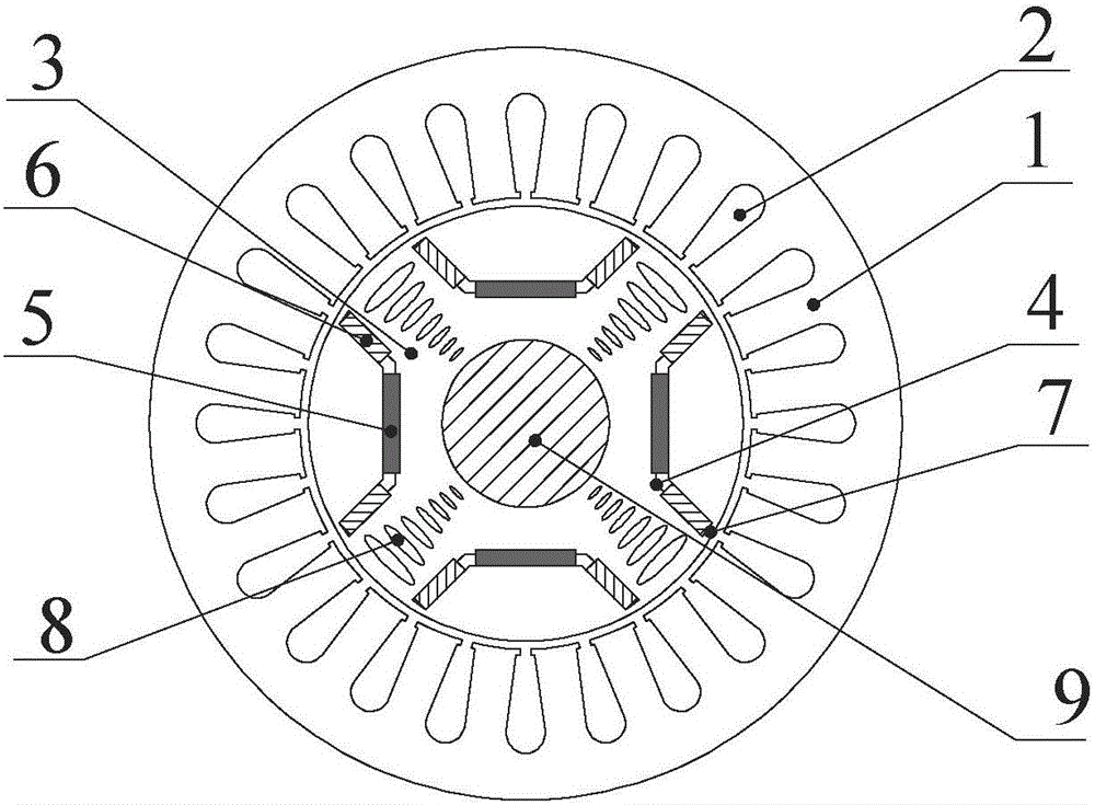
[0020] Specific implementation mode one: the following combination Figure 1 to Figure 3 Describe this embodiment, the magnetization type built-in U-shaped adjustable flux motor described in this embodiment includes a stator core 1, an armature winding 2, a rotor core 3 and a rotating shaft 9; the rotor core 3 is fixed on the rotating shaft 9, and is located Inside the core 1, the armature winding 2 is arranged on the stator core 1;
[0021] It also includes p U-shaped permanent magnet slots 4, p NdFeB magnetic poles 5, 2p AlNiCo magnetic poles 6 and p cross-axis magnetic barriers 8, where p is an even number, and the rotor core 3 is alternately and uniformly arranged along the motor circumference p U-shaped permanent magnet slots 4 and p cross-axis magnetic barriers 8, the U-shaped permanent magnet slots 4 and the quadrature-axis magnetic barriers 8 both penetrate the entire rotor core 3 in the axial direction, and the U-shaped permanent magnet slots 4 open toward the stator ...
Embodiment 1
[0025] combine figure 1 To illustrate this embodiment, the magnetization-increased built-in U-shaped adjustable flux motor includes a stator, a rotor, and a rotating shaft. The stator in the present invention includes a stator core 1 and an armature winding 2. The armature winding 2 is arranged in the slot of the stator iron core, and the rotating shaft 9 is made of cast steel, and the stator and shaft 9 are the same as those of conventional permanent magnet synchronous motors; the rotor includes U-shaped permanent magnet slots 4, NdFeB magnetic poles 5, AlNiCo magnetic poles 6, magnetic bridges 7 and cross-axis magnetic barriers 8 , the rotor is alternately and uniformly arranged with U-shaped permanent magnet slots 4 and quadrature-axis magnetic barriers 8 along the circumferential direction, and the U-shaped permanent magnet slots 4 and the quadrature-axis magnetic barriers 8 both run through the entire motor in the axial direction, and the openings of the U-shaped permanent...
Embodiment 2
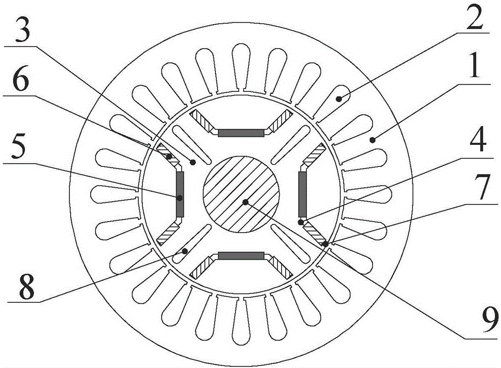
[0027] combine figure 2 Note that the difference between this embodiment and Embodiment 1 is that the quadrature-axis magnetic barrier 8 is a long strip-shaped groove arranged radially along the motor, with smooth ends at both ends, and its interior can also be made of non-magnetically conductive epoxy resin, carbon fiber, etc. , Non-conductive material filling.
PUM
 Abstract
Description
Claims
Application Information