
System and method for identifying product information

A product information and automatic identification technology, applied in the input/output process of data processing, instruments, electrical digital data processing, etc., can solve the problem of low efficiency in debugging lamps, and achieve the effect of improving the efficiency of installation and configuration

Inactive Publication Date: 2019-04-02
OPPLE LIGHTING +1
View PDF7 Cites 3 Cited by
  • Summary
  • Abstract
  • Description
  • Claims
  • Application Information

AI Technical Summary

Problems solved by technology

[0003] The purpose of the present invention is to solve the current problem of low efficiency when installing and debugging lamps, and propose a system and method for identifying product information

Method used


Image

  • System and method for identifying product information
  • System and method for identifying product information
  • System and method for identifying product information

Examples


Embodiment 1

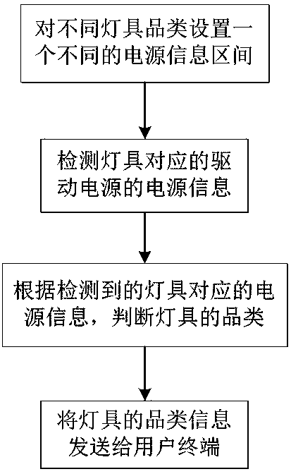
[0028] figure 1 It is a schematic diagram of a preferred method for identifying product information in an embodiment of the present invention. Such as figure 1 As shown, the method for identifying product information specifically includes:

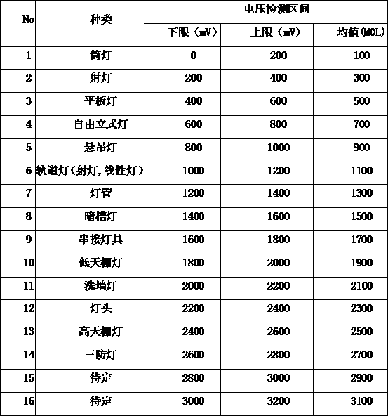
[0029] Step 1: Set a different power supply information range for different lighting categories. The power supply information interval is a voltage interval, a current interval, a frequency interval, one of the three, or a combination of two or more. The power supply information ranges corresponding to different lighting categories do not overlap. The following table shows the voltage range table corresponding to different types of lighting equipment.

[0030]

[0031] Table 1

[0032] As shown in Table 1, the corresponding voltage intervals of different types of lamps do not overlap. For example, the voltage interval of the seventh type lamp is 1200~1400, while the voltage interval of the adjacent eighth type recessed lamp is 1400~...

Embodiment 2

[0047] figure 2It is a schematic diagram of a preferred system for identifying product information in the embodiment of the present invention, such as figure 2 As shown, the system for identifying product information includes a lamp information collection module, a controller, and a user terminal.

[0048] The controller is used to set a different power supply information range for different lamp categories. The power supply information interval is a voltage interval, a current interval, and a frequency information interval, one of the three, or a combination of a plurality of them. A power supply information interval or a combination of multiple power supply information intervals can distinguish different lamp categories.

[0049] Table 1 is a table of voltage ranges corresponding to different types of lighting equipment. As shown in Table 1, the voltage ranges corresponding to different types of lamps do not overlap. The voltage range of the 8 types of recessed lights i...


PUM


Abstract

The invention relates to a system for automatically identifying product information. The system comprises a lamp acquisition information module, a controller and a user terminal, wherein different power information zone contrast tables are arranged in the controller and are used for setting different lamp types, the controller is used for sending power information needed to be acquired to the lampinformation acquisition module, the lamp information acquisition module is used for performing corresponding power information acquisition according to the required power information needed to be acquired and sending the acquired power information to the controller, the controller is also used for judging the lamp type according to the acquired power information corresponding to the lamp and thepower information zone contrast tables and sending the lamp information to the user terminal, the user terminal comprises a human-machine interface, and the human-machine interface is used for displaying the lamp information on the human-machine interface. The system is conveniently used for understanding types and working conditions of lamp products during the installation and application process, product distribution network, scene setting and other function configuration can be rapidly completed according to the information, and the efficiency is improved.

Description

technical field [0001] The invention belongs to the field of information identification, in particular to the field of identification of different lamp products. Background technique [0002] With the existing smart lighting equipment, after the installation of the lighting equipment is completed, when searching on the user's APP, only the number of lighting fixtures can be found, and the type of lighting fixtures cannot be identified. This requires the operator to identify the lighting fixtures first. Type or other lamp information, and then by renaming the icon of a lamp in the terminal device to distinguish between different lamps and lamp information, and manually complete the identification of lamp information. Obviously, the existing method for installing and debugging lamps is relatively inefficient and increases labor costs. Contents of the invention [0003] The purpose of the present invention is to solve the current problem of low efficiency when installing and...

Claims


Application Information

Patent Timeline
Patent Type & Authority Applications(China)
IPC IPC(8): H05B37/02H05B37/03
CPCH05B47/10H05B47/20H05B47/135G16Y40/30H05B47/19G16Y20/20G16Y20/30G01R19/2509G01R19/2516G01R22/10G01R31/2825G06F3/04817
Inventor 张国平朱健杨文寸加春
Owner OPPLE LIGHTING
Learn More